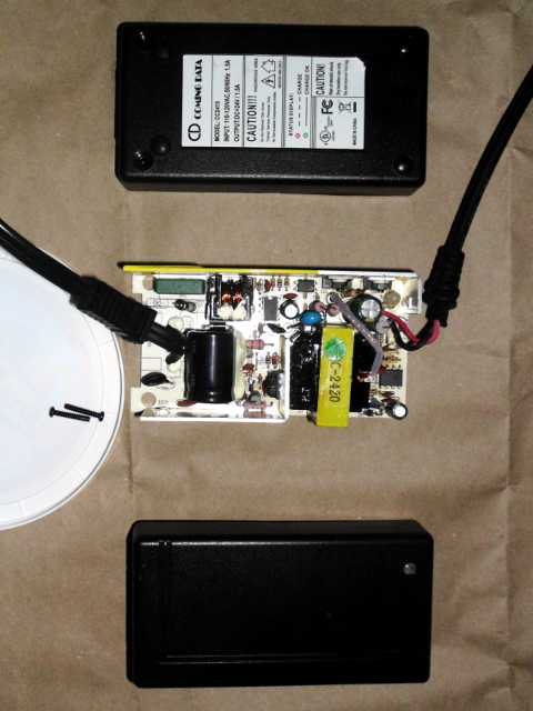
I got a charger for my 24-volt electric bicycle off eBay for about $12. The charger always seemed to run very hot when operating. Finally, after 6 months, it stopped working.
I already bought a replacement, but enjoy doing failure analysis. Possibly I can learn some lessons applicable to my solar bicycle.
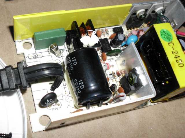
Ok, quiz for those who like a challenge. In looking at the schematic below, what components would you expect to fail if transistor Q1 burns up?
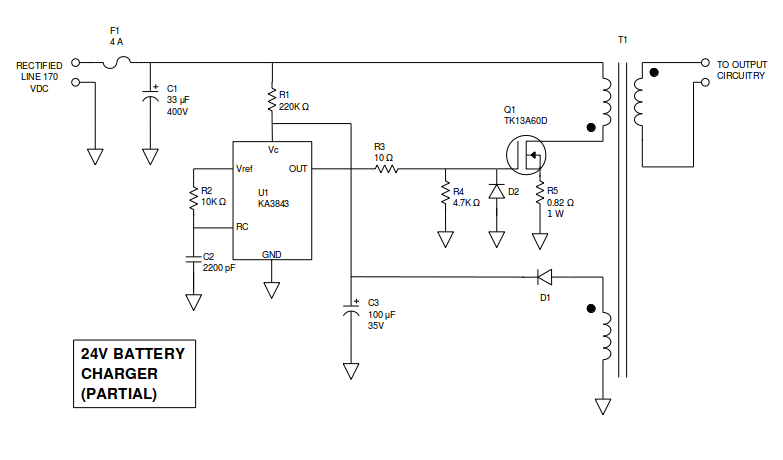
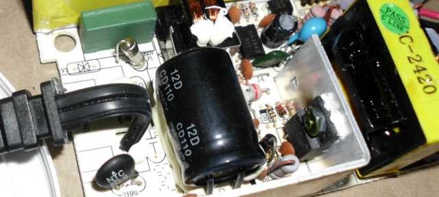
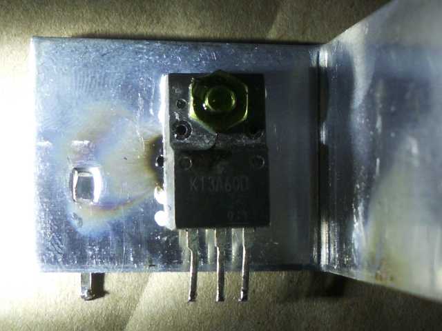
When MOSFETs overheat, my experience is that they short out – drain, gate, and source all become one resistive blob of a few ohms. I removed the transistor, and indeed, this was the case. The original part was rated at 600 volts, 13 amps, On Resistance of 0.33 ohm, and Input Capacitance of 2300 pF. I didn’t have that particular transistor on hand, but had a few 20N60C3 that were harvested from old power supplies. These were 600 volts, 20 amps, 0.19 ohm, and 2400 pF. Generally superior, and should run cooler. Same pinout, standard gate-drain-source, but the new part would need an insulating wafer since the drain was not isolated from the case. No problem. I put on a lot of heat sink grease.
All right, what else happens if all three terminals of Q1 are shorted together? Normally, the transistor only pulses on, so peak currents are limited by the inductance of the primary of T1. If the transistor is stuck on, huge currents will flow. But if everything is designed right, fuse F1 will do its duty and blow. In fact, F1 was open, and it protected the transformer primary from burning up. I didn’t have any 4 amp fuses on hand, but did have some 1 amp, so used one of those. My thinking was that the whole charger had a 36-watt output, and even if it was only 90% efficient, that would still be only 1/3 of an amp at line voltage.
I would not expect any of the source, drain, or gate of Q1 to get to any high voltage as long as R5 was intact. Even if 20 amps were flowing, that would still only be about 16 volts, well within what the connected circuits would withstand. R5 didn’t look burned. But the ohmmeter said otherwise. Lesson: metal film resistors can fail without looking burned.
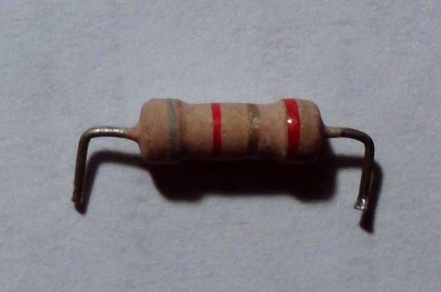
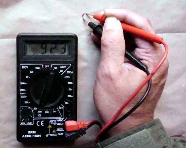
With R5 open, the voltage on the Q1 gate could zoom up to 170 volts. If that happened, R3 would pass the voltage along to U1, destroying the output stage, or possibly the whole IC. In fact, U1 was fried. I checked R3, expecting it to either be perfectly fine, or open, since it was a tiny, 1/16 watt part. Surprisingly, it read 923 ohms. I had to do a double take to make sure it wasn’t a 1k resistor. Was the third band brown or red? But only an idiot would use 1k as the gate drive resistor for a power MOSFET, so it must have been 10 ohms. Lesson: not only can metal film resistors fail without obvious visible indication, they can fail partially.
Initially, R1 provides the power to run the control IC. It takes a second or two to charge C3 up to the 16 volts needed to start U1. Before that, the OUT of U1 is floating, so R4 keeps Q1 from turning on and burning out. I put an ohmmeter across R4, and read 0 ohms. I wouldn’t expect a metal film resistor to fail shorted, so clamp diode D2 was suspect. I removed D2, and found that sure enough, it was shorted. But if it was shorted, how did dangerous voltages appear at the gate of Q1? Most likely what happened was D2 didn’t short immediately, but avalanched, heating up. First the output stage of U1 burned out, partially harming R3 in the process. Once U1 was gone, there was no more current flowing in R3, so the degradation stopped. Shortly thereafter, D2 melted from the heat, producing a dead short. Note that there was no visible damage to D2, which was a 1N4148 type switching diode. Lesson: diodes can fail shorted, with no visible indication.
It takes only 1 mA to start U1, but it draws 17 mA while running. To avoid using a lower resistance for R1 and making it a huge power resistor, this design uses R1 only for bootstrap power. A dedicated winding on T1, along with D1, provide running power once the IC comes up. I was initially concerned that high voltage may have gotten through the IC during failure and harmed D1 and C3, but they tested out fine.
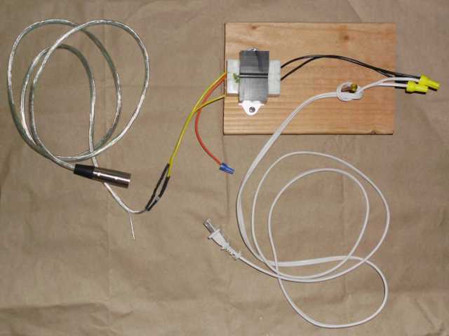
U1, the KA3843A pulse-width modulator IC, was the only part for which I had no substitution. I added one to my next Mouser order for about 60 cents. No rush. After all, I had already ordered a replacement charger. For the few days while waiting for the replacement, I threw together a trickle charger. Fortunately, I had everything; nothing needed to be purchased. It consists of a 24-volt transformer, with a half-wave rectifier. I had to dust off my calculus to figure out that a 137 ohm resistor should provide an average charging current of 75 mA or so, which hopefully could be left connected indefinitely to the 12AH battery pack without damage. A nail on the board provided strain relief for the line cord, which was simply attached to the transformer with wire nuts.
The repaired charger now works, but I think I’ll take it apart and salvage some of the parts. In fixing it, I’ve noticed some weaknesses in the design, and it still runs hot, even after being repaired. The new charger, on the other hand, barely gets warm.
A general lesson from this exercise is that in switching supplies, when the main switch fails, it will generally take other components with it.
Another general lesson is that it’s not worth fixing a switching supply, unless you happen to be working for the manufacturer and are feeding back the findings to engineering for improvement. A brand new supply is $12, so even if I was working at minimum wage, it would not be worth it.