Replace Fluorescent Backlight on a Laptop with LED

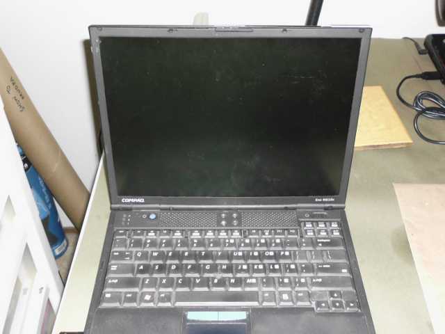
My laptop broke. To be precise, the backlight on the LCD screen went out. That pretty much made the whole thing unusable. It was an older Evo N610c, not really worth fixing. But I decided to see if I could do a low-cost hack to repair the backlight.

This is what the laptop looked like when it was ON.  Pretty much the same as when it's off, except for the sounds of hard disk and fan.
This is what the laptop looked like when it was ON. Pretty much the same as when it’s off, except for the sounds of hard disk and fan.

First, I had to take the darned thing apart.  Fortunately, HP had a service manual posted online which I could refer to.  The thing was full of small screws and difficult to loosen parts.  Some things like the LCD panel were held on by metal tabs that had to be bent aside, or by tape.  I never want to do this again.

The LCD panel after removing it from the laptop.  Wasn't easy.
The LCD panel after removing it from the laptop. The white bar near the bottom of the panel is a plastic sleeve holding an inverter, which generates high voltage to light up the fluorescent tube.

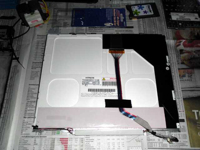
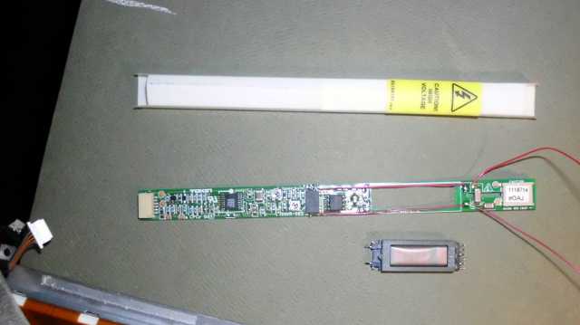
After a lot of fussing, I was able to remove the backlight. I tried to make the tube flash with a high-voltage flyback spike generated by a transformer and a battery. No dice.

This was the original backlight, a 1mm diameter tube.  I believe it's defective.
This was the original backlight, a 1mm diameter fluorescent tube. A penny is in the picture for scale, and to the right of the penny, a surface mount LED.

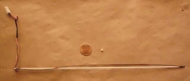
Unless I was really lucky, the chances of finding another backlight of the original type were low. So I decided to jerry rig a white LED and resistor as a backlight.

A surface mount LED was harvested from a surplus lighting strip.  I soldered on a tiny 100-ohm surface mount resistor for current limiting.
A surface mount LED was harvested from a surplus lighting strip. I soldered on a tiny 100-ohm surface mount resistor for current limiting.
If you look carefully, you can see the LED at the end of the red wires.
Here is the LED mounted at the bottom of the display, feeding right into the plastic light transmission plate.  I held the assembly in place with scotch tape.
Here is the LED mounted at the bottom of the display, feeding right into the plastic light transmission plate. I held the assembly in place with scotch tape.

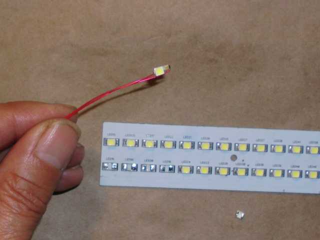
The LED needed about 2.5 volts at 25 mA. I needed to wire a different power source. Fortunately, the inverter supplying the original backlight already had 5 volts on the board. It was a simple matter of jumpering over the needed voltage. One drawback of this arrangement is that the backlight can never be turned off, now. I suppose I could have tapped into the backlight control signal and wired in a transistor to turn off the LED, but that would be getting too fancy.

This is the inverter, taken out of the plastic sleeve.  The transformer has been removed, and +5V wired directly to the output.
This is the inverter, taken out of the plastic sleeve. The transformer has been removed, and +5V wired directly to the output.
Okay, it looks sort of like a searchlight at the bottom.  It's still readable, and enough for the purpose.
Okay, it looks sort of like a searchlight at the bottom. It’s still readable, and enough for the purpose. I just have to visualize that I’m watching a broadway show, lit by stage lights.

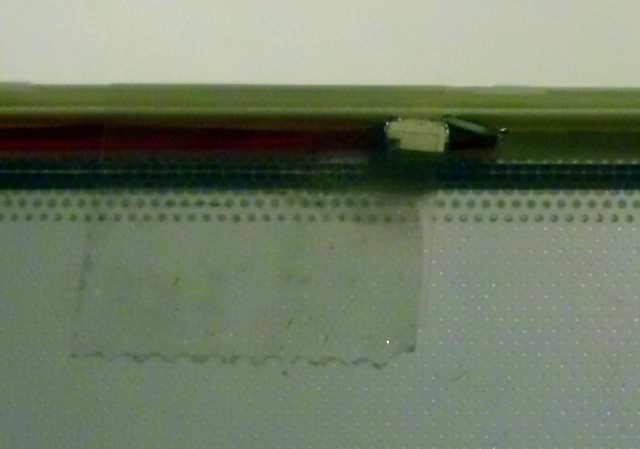
Well, the hack doesn’t win any awards for beauty.  It probably would have looked nicer if I used 3 LEDs across the bottom.  But there’s no way I’m going back in there.

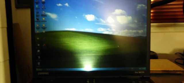
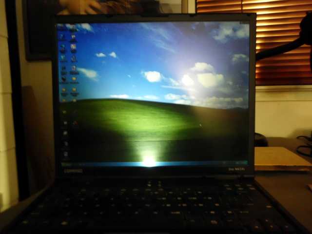
It’s readable; enough that I could install VNC or remote desktop, and use the laptop remotely.

(Visited 928 times, 1 visits today)

Leave a Reply

This site uses Akismet to reduce spam. Learn how your comment data is processed.