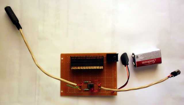
I recently got a couple computer headsets at a local flea market. Just the thing for a secret project I’m working on!

I connected the pink stereo mini-plug to the LINE IN of my recording device, and got silence, no matter how loudly I screamed into the mike. Funny, it worked fine connected to the MIC IN jack of my computer… On the internet, I quickly discovered how most inexpensive computer microphones work. They’re basically resistors of maybe 10k ohms, that vary with sound. The microphone produces no voltage of its own. The computer’s microphone input is designed to put a little bit of bias current through that resistor, and amplify the AC component of the resulting voltage. So I threw together the following circuit:
Only the left channel of the circuit will be discussed, since the right channel is analogous.
R2 provides the bias for the microphone input, and when there is loud singing into the mike, the voltage across the mike varies by perhaps 50 mV peak-to-peak.
C2 blocks the DC component of the signal, passing the AC portion into the amplifier. The only reason I used 100 µF was that I had a bunch of these ceramic capacitors on hand, and they were 1210-size surface mount parts, so fit easily on the breadboard. Probably 1 µF would have been enough. No electrolytic capacitors were used at all in the design. The 6-volt rating is technically too low for use with a 9-volt supply, as the full supply voltage less 2 volts can appear across the capacitor if the mike is not plugged in. However, I can always switch to capacitors with higher voltage ratings if the existing ones burn out. In a hobby situation, I can do things that I would never have done for a production design.
U1a is a general purpose op-amp. In this configuration, the signal is inverted at the output, but that is fine for this application. The ratio of R4/R3 sets the gain at 20 (10 dB).
Since a single-rail power supply is used, the operating point of the amplifier must be set further above ground than that largest signal excursion, to avoid clipping. As the output signal is expected to have a maximum of about 1 volt peak-to-peak, the operating point must be at least 0.5 volt above ground. This is accomplished by feeding a voltage reference into the + input of the op-amp. If the non-inverting configuration of amplifier was used, it would have required two independent references, one for each channel. By using the inverting configuration, the voltage reference can be shared between the two channels, resulting in lower parts count. The most straightforward reference would have been a resistive divider between supply and ground, but since I want a visible indication that the circuit was on anyway, LED1 provides a reference of about 2 volts without additional parts. C1 at 2.2 µF has far more capacitance than needed. Given the minuscule offset current of the op-amp, and the slow nature of audio signals, possibly no capacitor was needed at all, or a simple 0.01 uF would have been fine. The only reason I used 2.2 µF was because I needed at least a 20 volt rating, and had a reel of 2.2 µF in 1206 size.
C3 blocks DC from the output. This is not strictly necessary going to the LINE IN jack of audio equipment, which tends to have its own coupling capacitor. However, if headphones or even a speaker are ever connected directly to the output, C3 prevents having approximately 2 volts across the output at all times. Again, the 100 µF value is severe overkill – 1 µF would probably have been fine.
The power supply voltage is not critical for this circuit. It works well with 5 volts as well as 9 volts. It may work with a 3-volt supply, and there is no reason why it should not work at 15 volts, although the voltage ratings of some of the capacitors may need to be adjusted. In fact, the first prototype was powered by an Apple iPad 2 charger, but put out an annoyingly loud squeal at the output due to supply switching noise. Using a 9-volt battery avoids the switching noise issue. Power dissipation is low – the greatest power dissipated in the circuit is from the indicator LED. If that was omitted in favor of a high value resistive voltage divider, the already lower power drain could be reduced even further.
Design notes are here.