On a recent breadboard for the power transfer controller, I was getting puzzling results. One explanation for the discrepancy might have been that the electrolytic capacitor actually had much more than the label value of 1000 μF. That seemed possible, as usually no one complains if a bulk bypass capacitor has more capacitance than advertised. It’s like getting a 16 ounce box of cereal, and finding out that it really has 20 ounces in it. All the better.
But how to measure capacitance? For a smaller capacitor, I could build a resonant circuit and measure the frequency. But for 1000 μF, there was a simpler way, and it was easy to make from parts already on hand.
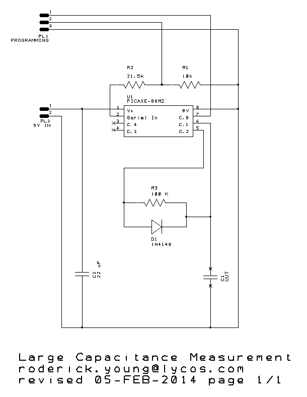
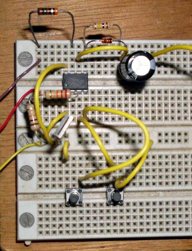
Above is the circuit I used. The PICAXE processor is a powerful controller, amazing for its $1.50 price tag. It has multiple 10-bit A/D converters on board, and an embedded serial port.
At the start of the program, the controller brings pin C.2 high. C1, the unit under test (UUT), begins to charge through R3. D1 is not strictly needed, but provides for quicker charging. While this is going on, the A/D input on pin C.1 is watching the capacitor voltage. The A/D range is 0 to 1023 units, with 1023 being the full supply voltage. When the voltage reaches at least 1020 units, the program waits for me to push the start button.
When I push the start button, pin C.2 goes to 0 volts, and the UUT starts discharging through R3. (Fortunately, the A/D converter input has very high impedance compared to 100k, and does not significantly disturb results.) The controller then reports the time it takes for the voltage to decay from 1000 units to 368 units. These numbers are a very intentional choice, because they represent a decay from 100% to 36.8%, or 1/e. Electrical engineers will recognize it as one time-constant, τ, and remember that τ = RC. Since τ is reported in mS, and R is 100 kΩ, it works out that every 100 mS elapsed translates into 1.0 μF. In fact, I tried a 105 (1 μF) ceramic capacitor, and it read 1.12 μF.
In order to read a capacitor as large as the electrolytic, I had to use a smaller value (10 kΩ) for R3 so that the timer wouldn’t overflow. So, what was the actual value of my brand-new 50 volt, 1000 μF, 105 ºC, aluminum electrolytic capacitor? 1048 μF.
Design Notes are here.
The controller program in BASIC is here.