When I was in high school, if someone said they dropped an oscilloscope on their foot, it would be cause to go to the office for first aid, or possibly even call an ambulance. Today, if I dropped this scope on my foot, I would be more worried about the scope than my foot.
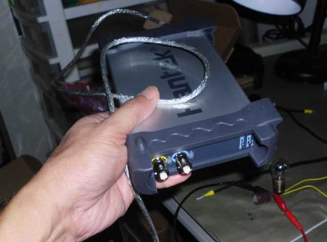
The Hantek 6022be digital oscilloscope weighs 13.3 ounces, and is a wonderful example of how technology gets cheaper and better with time. The line cord alone of an old analog oscilloscope might outweigh this tiny model. And by the way, the Hantek has no line cord – it draws all it needs from USB, though its PC connection. I bought this instrument on eBay for $69.14, with free shipping. Not since Adventures in Babysitting have I had such low expectations for something, and been so pleasantly surprised. For that paltry price, I got the scope, two probes that are settable for x1 or x10, and the software.
This model has most of the features of the analog scopes of yesteryear, including a built-in calibration source. It is, of course, a storage scope, and can send output directly to a printer, or save it in a variety of file formats, including bitmap and spreadsheet. There is also the handy feature of time, voltage, and frequency measurement by just dragging a cursor.
My first use of this scope was to debug an overheating problem on a DC-DC converter circuit. This was a tough problem to diagnose without a scope, but is now trivial. I was blind, but now I see. Below is the troublesome driver circuit for the main power MOSFET. R5 is driven directly from a processor output pin.


Okay, so I got rid of the resistor, and drove the MOSFET directly from the processor pin:

The next thing I tried was a complementary pair of small MOSFETS as a driver:


The scope didn’t come with a manual, but I’m slowly figuring out how to use it. To move the channel 1 trace up and down, all I have to do is drag the yellow “1” label up and down. The trigger level can be adjusted in a similar manner. To pan the trace right or left, I simply drag it, like a Google map. Below is a trace with the ringing dragged up where we can see it:

Some of the ringing above is a consequence of my test setup, which has a foot-long wire going to the gate of the transistor, and a foot-long ground return. The following trace was taken at the driver instead of the gate of the transistor:

I put a 15Ω resistor between the complementary pair and the gate of the power MOSFET, and measured at the gate again:

It’s advertised as a 20 MHz scope, but that’s basically the Nyquist rate, so I thought it was marketing hype. But then, I took the following trace:
And now, some of the drawbacks of the 6022BE:
- There is only DC coupling. If you want AC, you’ll need to build your own test jig.
- The triggering has no noise filter on it, so is very erratic. The trace buffer is usually deep enough to capture what you want, but it might take several tries, and/or you might have to scroll through a lot of data.
- Speaking of scrolling, there are no scroll bars, a serious user interface deficiency. As the software stands today, you can drag the screen right or left, but with a deep buffer, may have to drag literally hundreds of screens to get to the point of interest. What is really needed is the ability to zoom in on a chosen area. Perhaps that will be added in a later version of software.
- The software does have the ability to export the data buffer as a text file, so maybe someone could write a utility to display and zoom the trace offline. However, the values output in the text file might need adjustment. I measured a known 5.2 volt signal, and the text file said it was 6.2 volts.
- Triggering is not reliable, especially at high speed sweeps, and especially in single sweep mode. I suspect that what the software does is blindly capture a data buffer, then scan to see whether there is a trigger event in it. If no trigger is found, the software then captures another data buffer. Needless to say, at high sweep rates, there is a lot of deadtime between capturing buffers while the software is busy looking at the captured buffer. If a trigger event should occur within this deadtime, the trigger would be missed. For repetitive signals, this is less of an issue, as sooner or later, by plain dog luck, a trigger event will be captured.
- The scope is NOT isolated from USB ground, which on a computer is typically connected to the ground on the wall plug. You cannot connect the ground clip of a probe to (say) line voltage to take a reading. You’ll need to either use an isolation transformer, or a laptop running on batteries (not plugged in) to do this sort of thing without blowing something up.
- There is no mention in the specs, but it seems that actual input voltage to the scope is limited to 5 volts. This is not surprising, since the USB voltage is 5 volts. So if you use the included 10:1 probe to measure something that is (say) 75 volts, it will read as 50 volts. If you want to measure between 50 to 500 volts, you need a 100:1 probe, not included. Of course, if you wanted to be cheap about it, you might just put a 90 MΩ resistor in series with the included probe.
- The software only works on Windows XP and later. It does not load on Windows 2000. If you have Windows 7 or later, you need to go to the Hantek site to get drivers that are not on the included CD. There is OpenHantek software that runs on linux, but it does not support the 6022BE at this time (2013). If you are handy with software, you could make a lot of friends by porting this open source software to work with the 6022BE. There is also some software called Open6022BE being developed here by a user named “RichardK,” with documentation by “Matchless,” and testing from the community at large. At this writing (March 2014), the software is still in Beta, but I find it so much better than the stock software, that I already use it on my home bench. For your convenience, I have mirrored the Open6022BE software and source here. UPDATE (22-Dec-2016): I have written my own open source alternative software. You can get BasicScope here.
- Do not expect any support from the manufacturer in China. Their site is very sparse with English help.
- The scope trades off sample rate and sample size; you cannot get the 48 MHz sampling at the same time as the 1 MB buffer. Once you set the sweep rate (time per division), the sample rate and size are fixed per the table below. Data from Rick Law on this forum, plus a bit of data I filled in for completeness.
| Time per Division | Sample Rate | Sample Size (per channel) |
|---|---|---|
| 50 mS or longer | 1 MHz | 1,047,552 |
| 5 to 20 mS | 1 MHz | 523,264 |
| 50 µS to 2 mS | 1 MHz | 130,048 |
| 20 µS | 4 MHz | 130,048 |
| 10 µS | 8 MHz | 130,048 |
| 5 µS | 16 MHz | 130,048 |
| 2 µS or shorter | 48 MHz | 1,016 |
In spite of the above, I’m still super-pleased with my purchase.