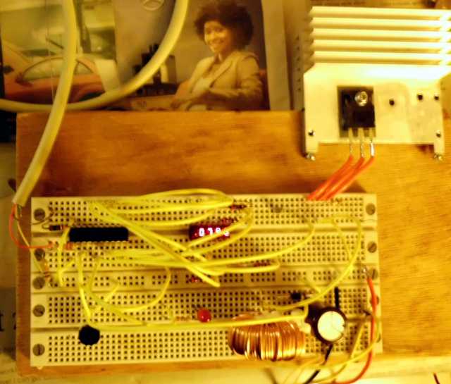
A couple months ago, I discovered the PICAXE embedded processor. It’s supposed to be designed as an educational tool, but I’m realizing that the chip is so versatile, I can make it do real work. Here is basically what is on the chip:
- PIC processor that runs at 32 MHz
- Oscillator with resonator (no external components)
- 2048 bytes of FLASH for program
- 512 bytes of RAM
- 256 bytes of non-volatile EEPROM
- RS-232 UART, through which device can be programmed
- Sixteen programmable I/O pins
- Precision voltage reference
- Eleven 10-bit Analog to Digital converters, which can also be used as touch sensors
- Digital to Analog converter
- Pulse width modulator
- BASIC interpreter built-in
- Keyboard interface
- i2c interface
- one-wire bus interface
- infrared interface
- music generator with tunes
And the development platform, including simulator, is free. So basically, for about $3, you just connect this thing to your serial port, and away you go. It’s like an Arduino board, only all on one chip, and cheaper. Did I mention that it can run multiple tasks? Unbelievable.
I have several projects planned for the PICAXE. One is the power transfer controller for my solar bicycle. Watch this space for other projects, one of which will incorporate the stepper below.
Here is the program, if anyone is interested:
; try stepper motor
; outputs	C.0 = A (white)
;		C.1 = B (red)
;		C.2 = ~A (green)
;		C.3 = ~B (brown)
;
; inputs C.7 = CCW button
;        C.6 = CW button
;        C.5 = START button

; comipler directives only apply to PICAXE programming editor
; #com 1
#picaxe 20m2
#no_data		; do not bother to download EEPROM data

symbol	StepValue = b0
symbol	DrivePattern = b1
symbol	StepMask = 7		; =3 for 4 step pattern, =7 for 8-step

; Initialize
	pinsB = %10000000
	dirsB = %10000000		; for debug, drive LED's too
	pinsC = %00000000
	dirsC = %00001111
	pullup $E000	; 3 input buttons
	StepValue = 0

main:
;
; Do some manual positioning
;
	button C.7, 0, 10, 1, b3, 0, SkipCCW
		; increment by one ccw
		StepValue = StepValue + 1 and StepMask	; count up modulo 4
		call StepMotor
SkipCCW:
	button C.6, 0, 10, 1, b4, 0, SkipCW
		; decrement by one cw
		StepValue = StepValue - 1 and StepMask	; count up modulo 4
		call StepMotor
SkipCW:
	button C.5, 0, 10, 2, b5, 1, RunMotor
	pause 100
	goto main

RunMotor:
	for b4 = 1 to 2

		for b3 = 1 to 100
			StepValue = StepValue + 1 and StepMask	; count up modulo 4
			call StepMotor
			pause 1	; pulse for 1 mS
	;	pinsC = 0	; turn off for a moment - can only do with single phase
	;	pause 500
		next b3

		for b3 = 1 to 100
			StepValue = StepValue - 1 and StepMask	; count up modulo 4
			call StepMotor
			pause 1	; pulse for 1 mS
		next b3

	next b4

	; turn coils off to save power
	pinsC = $0

	goto main

; advance motor one to match StepValue
StepMotor:
	lookup StepValue, (%0011, %0010,%0110, %0100,%1100, %1000,%1001,%0001), DrivePattern	; half-step
;	lookup StepValue, (%0011, %0110, %1100, %1001), DrivePattern
;	lookup StepValue, (%0001, %0010, %0100, %1000), DrivePattern
	pinsC = DrivePattern
	return
(Visited 197 times, 1 visits today)