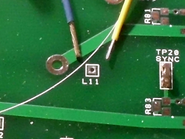
During design of a recent PC board, I did a quick search for “AWG diameter,” and was presented with a simple table listing the diameter of each gauge. When the boards came back, I found that the wires I had did not fit into the holes. That’s when I learned that wire diameter depends not only on the AWG size, but on the number of strands.

It makes sense, now that I think about it. The most important characteristic of a wire electrically is how much current it can carry, not its total diameter. So an electrical engineer can specify, say, #20 wire, and be assured of a certain current carrying capacity. #20 solid wire is nominally 32 mils in diameter. I had therefore specified a 35 mil hole. What I found out later by searching “AWG diameter stranded” is that wire sold as #20 stranded can be 10/30 (10 strands of #30, 35 mil total diameter), 19/32 (37 mil), 26/34 (36 mil), or even 41/36 (36 mil).
Fortunately for me, the wire was an inductor winding, and I should have been using solid wire anyway. When solid wire was used, everything fit perfectly.
In summary, in the future, when I want a PCB hole to solder a wire into, I will take the total outer diameter of the wire I intend to use, and add 3 mils.
Note to other novices like me: when specifying a FHS (finished hole size), you don’t need to worry about drill sizes or plating thickness unless you’re doing the boards yourself. When you go out to a contract board maker, Finished Hole Size means exactly that. If they say their holes are +-3 mils, then for a 32-mil wire, a 35-mil or larger hole should be fine.