The PICAXE processor, based on the PIC, has a lovely hardware pulse width modulator (hpwm) on board, which is programmed via the hpwm command. There are 3 modes available: single, half-bridge, and full-bridge. Only half-bridge will be discussed in this article.
A few things about the feature were confusing to me initially, so I’m documenting some of my learnings here.
Not all PICAXE parts support hpwm. Notably, the ultra-cheap 08M2+ does not – probably because there are not enough I/O pins to support full-bridge mode. In this example, a 14M2+ (firmware version 6.A) is used.
The outputs in half-bridge mode are on the “hpwm A” and “hpwm B” pins of the chip. (Some early versions of the PICAXE documentation had a typo that put one of the outputs on an incorrect pin.) The active time of the “A” phase is specified by the duty parameter, and the “B” phase is roughly complementary to “A”. The pins “hpwm C” and “hpwm D” are not used by the pulse width modulator in half-bridge mode, and may be used for other purposes if desired.
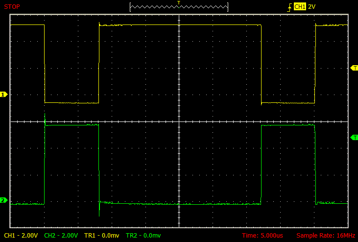
In the code below, the fundamental clock frequency is set to 32 MHz, or 31.25 nS per cycle. This is the unit of measurement for the duty parameter. So a duty of 768 means that the pulse will be active for 768 * 31.25 nS = 24000 nS = 24 μS. The unit of measurement for the period parameter is 4 clock cycles, and the formula includes an offset of 1. So the period of 255 corresponds to (255+1) * 4 * 31.25 nS = 32000 nS = 32 μS. In sum, the waveform in the example will have a 24/32 = 75% duty cycle. The pwmHHHH sets the polarity of the output pulses to active high. The deadtime parameter will be discussed later.
; This program will show the half-bridge mode of the hardware
; pulse width modulator on the PICAXE.
;
; 08-MAY-2015; Roderick.
;
#picaxe 14m2
#no_data

    symbol deadtime = b0
    symbol period = b1
    symbol duty = w3

    setfreq m32 ; 32 MHz oscillator frequency

    deadtime = 0
    period = 255
    duty = 768

    hpwm pwmhalf, pwmHHHH, deadtime, period, duty

waitforever:
    goto waitforever

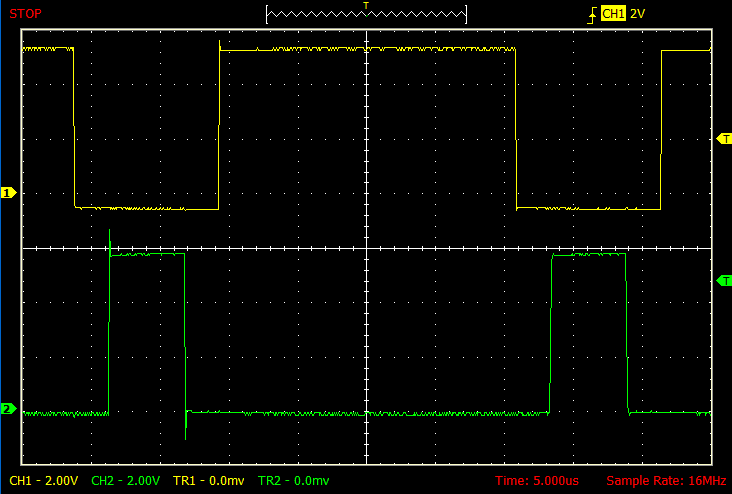
To generate the next trace, this change was made to the program:
deadtime = 20
The dead band delay (deadtime) causes a delay between one phase going inactive and the next phase going active. The unit of deadtime consists of 4 fundamental clock cycles. In the case below, a deadtime of 20 translates to 20 * 4 * 31.25 nS = 2500 nS = 2.5 μS. Note that in the trace below each of the “A” and “B” active pulses is 2.5 μS narrower than before. Incidentally, specifying a deadtime that is too large can completely annihilate the active pulse of either or both phases.

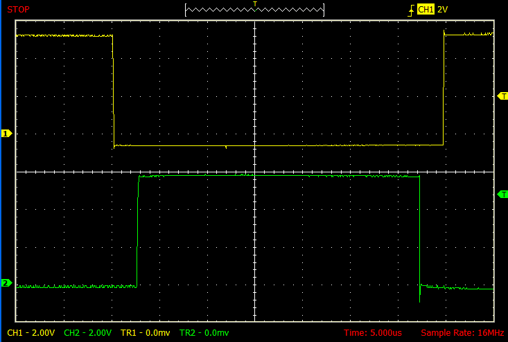
As previously mentioned, the period of the waveform above is 32 μS, and this is, in fact, the maximum possible for a 32 MHz clock frequency. To get a slower waveform, a prescaling divisor of 4, 16, or 64 can be added. The keywords for these are pwmDIV4, pwmDIV16, and pwmDIV64, respectively. (Early documentation had incorrect keywords.) This line of the program was changed as follows to generate the next traces:
hpwm pwmDIV4, pwmhalf, pwmHHHH, deadtime, period, duty

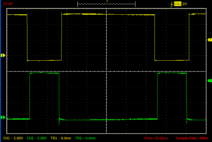
Below, the same trace zoomed out by a factor of 4, showing the similarity to previous traces in this article. The deadtime of 20 is still based on the fundamental clock frequency, and is unaffected by any prescaler such as pwmDIV4. If more deadtime is needed than can be set according to (127+1) fundamental clocks, then the fundamental clock itself must be slowed with the setfreq command.

Additional note: The PICAXE documentation (as of 10/2015) says that hpwm single mode is not supported on 14M2 or 20M2. However, as far as I could tell, it worked just fine on a 14M2+. Possibly their documentation needs updating.