I have a need to measure home-wound inductors in the range of 10 – 100 μH (It’s for the power transfer controller of the solar bicycle).
On eBay, I found quite a few “universal” 12864 testers based on the atmega328 for as low as $13. Those would measure L, C, R, as well as semiconductors. However, I could find no spec in the descriptions for the inductance measurement range. The image here suggests that the maximum resolution is 0.01 mH (10 μH) – not really good enough if I want to distinguish between, say 13 μH and 18 μH.
My final choice was the DM4070. At $31.50 (US seller, free shipping), it was the cheapest LCR meter that would do what I needed.
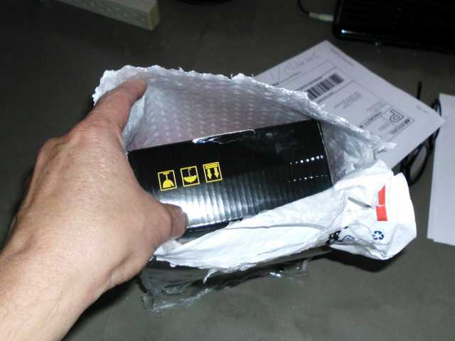


Included with the meter was a poorly-written manual. Perhaps it was translated from Chinese? The translation was intelligible, as long as I used imagination.
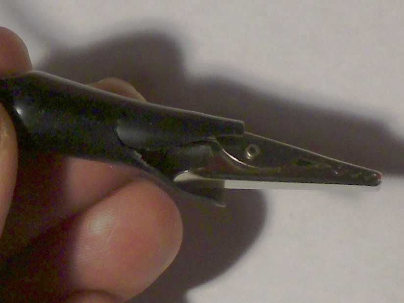
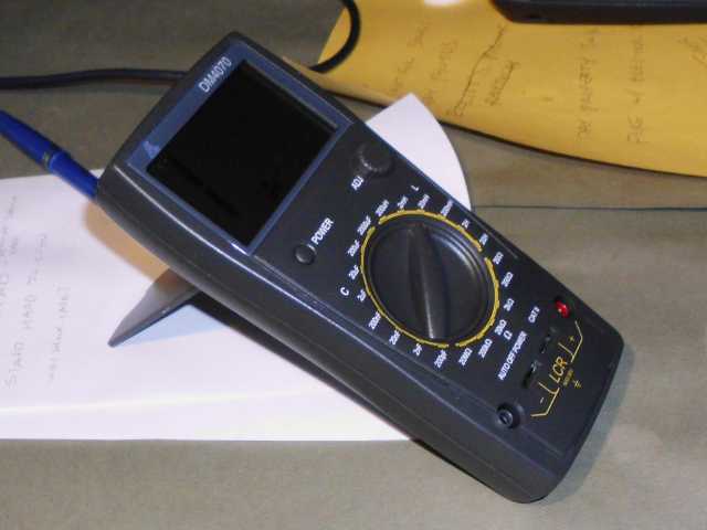
After the quick visual examination of the unit, I pressed the power button. Nothing. Maybe batteries weren’t included? I slipped off the shock case, removed a philips screw, and looked into the battery compartment.
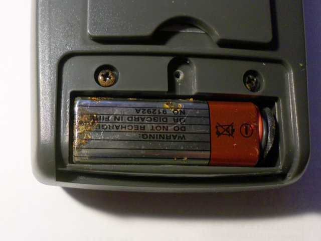
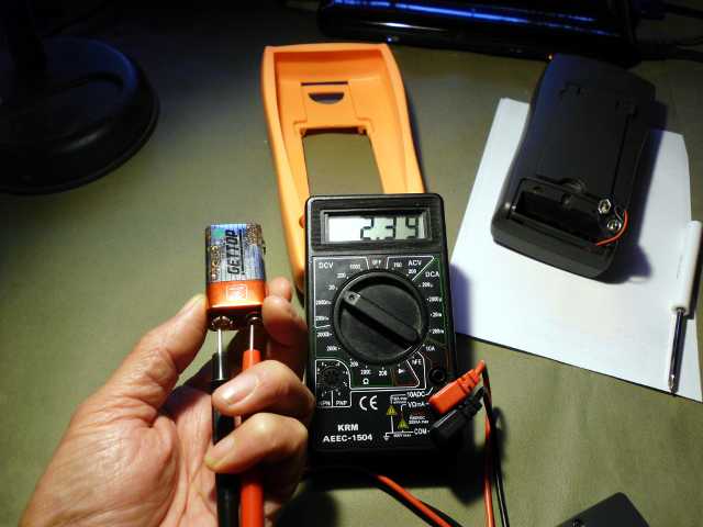
I put a fresh 9-volt battery in, and the DM4070 powered up fine. Fortunately, none of the chemical leakage from the battery appeared to have gotten into the actual device. I’m wondering: does the DM4070 go through batteries quickly? It’s supposed to automatically sleep after being idle for a few minutes, but I haven’t personally witnessed this behavior, yet. I’ve been turning the meter off after every use.
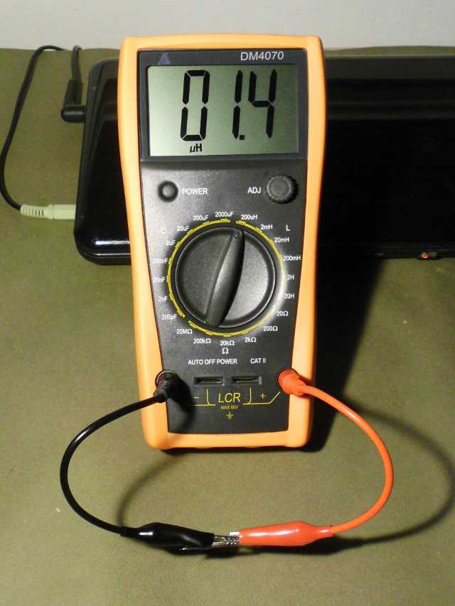
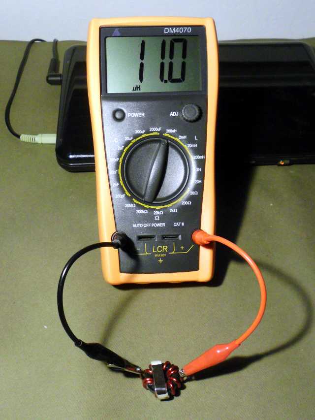
My first measurement was of a known inductor. I first shorted the test leads together to determine the lead inductance. Actually, the operation manual says not to do this, but I think that warning was intended for capacitance measurements, or perhaps to save power.
Next, I measured some capacitors. I tried a few and found the measurements to be mostly good. Possibly the measurements of high value capacitors were a little low. The DM4070 reported my 1000 μF capacitor as being 953 μF. I might have chalked that up to component tolerance, except that I had measured that lot of capacitors previously with my a test jig of my own design, and believed that they were more like 1100 μF.
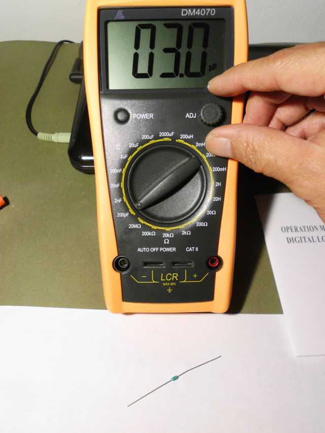
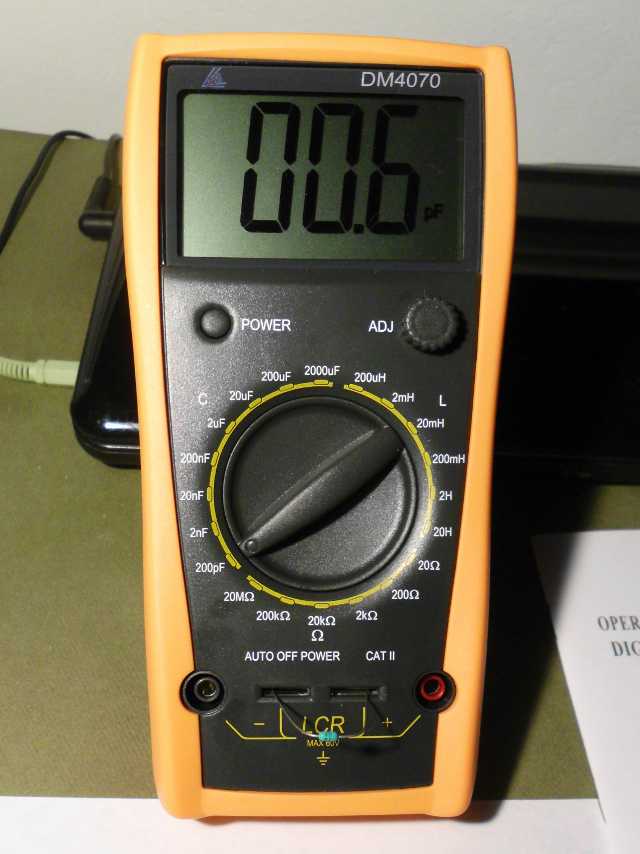
Finally, I measured some resistors. The readings were quite accurate, except on the 20 MΩ range, where they seemed to read 5% high. Some of it might have been component tolerance. Actually, I’m pleased to have a 20 MΩ range at all – cheap digital voltmeters often top out at 2000 kΩ (2 MΩ). The 2 MΩ range is actually missing on this meter, so if you need to measure things in the hundreds of kΩ with precision, this is not the meter for you.
One thing that I noticed is that on the high value ranges, the readings took a few seconds to settle to a final value. This is fine, as long as one knows to wait.
Here are the test results:
| Component | Labeled | Reading | Notes |
|---|---|---|---|
| Inductor | 10 μH -0+30% | 9.6 μH | After subtracting 1.4 μH for leads |
| Inductor | 30 μH -0+30% | 29.7 μH | After subtracting 1.4 μH for leads |
| 8.5V winding | 43.9 mH | torroidial transformer secondary | |
| 14.9V winding | 150.7 mH | torroidial transformer secondary | |
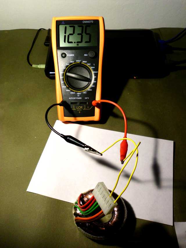
| 115V winding | 3.27 H | torroidial transformer primary | |
| 105V winding | 2.59 H | torroidial transformer primary | |
| 220V winding | 12.35 H | above 2 windings in series | |
| Capacitor | 75 pF | 77.3 pF | |
| Capacitor | 470 pF 5% C0G | .477 nF | ceramic |
| Capacitor | 2700 pF 5% | 2.73 nF | polystyrene |
| Capacitor | 1 μF | 1.001 μF | ceramic |
| Capacitor | 4.7 μF | 5.05 μF | solid tantalum |
| Capacitor | 100 μF | 96.3 μF | aluminum electrolytic |
| Capacitor | 470 μF | 457 μF | aluminum electrolytic |
| Capacitor | 1000 μF | 953 μF | aluminum electrolytic |
| Resistor | 0.62 Ω 1% | 0.62 Ω | After subtracting 0.08 Ω for leads |
| Resistor | 11 Ω 5% | 11.37 Ω | After subtracting 0.08 Ω for leads |
| Resistor | 137 Ω 1% | 136.9 Ω | |
| Resistor | 562 Ω 1% | .561 kΩ | |
| Resistor | 16.2 kΩ 1% | 16.18 kΩ | |
| Resistor | 33 kΩ 5% | 33.1 kΩ | |
| Resistor | 180 kΩ 5% | .19 MΩ | |
| Resistor | 2.2 MΩ 5% | 2.36 MΩ | |
| Resistor | 3.3 MΩ 5% | 3.43 MΩ |