The used trailer from the estate sale actually had nice tires. But I couldn’t figure out how to get them off. The end caps on the axle appeared to be welded on.
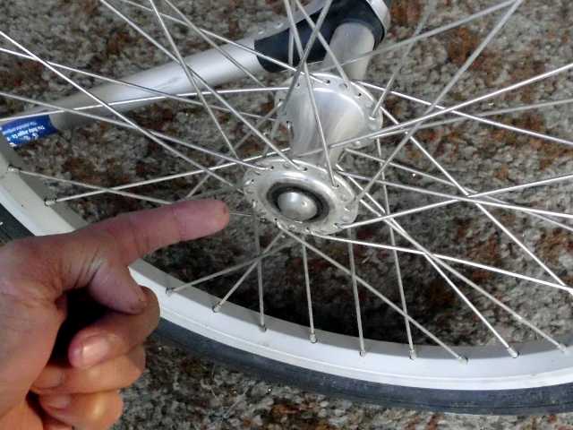
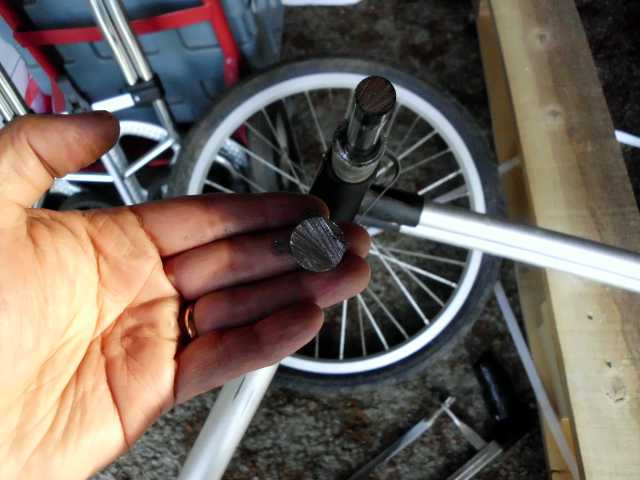
By the way, the name of the trailer I salvaged was “Baby Jogger II-20 Alloy.” It was severely overdesigned, with 36-spoke 20″ wheels, and a 1/2″ steel axle. Stronger than most bicycles. The label said it was rated for 100 pounds, but I would not be surprised if it could bear triple that.
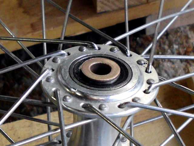
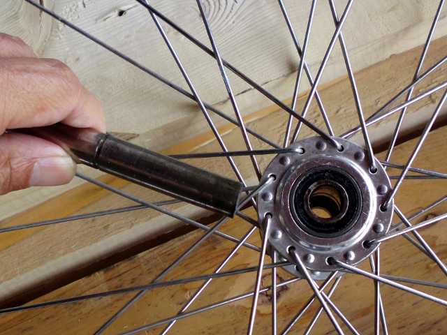
If you look carefully at the picture above, you’ll see the bearing. The little ring in the middle spins freely, while the black part around it is fixed to the outer metal ring, which is press-fitted into the hub. In other words, nothing spins except the tiny, innermost ring.
My first thought as to how to mount this wheel on the trailer involved putting a simple 1/2″ threaded rod through the middle, with nuts on either side. I didn’t like the idea of the wheel possibly spinning on the threaded rod. Also, if I tightened the nuts down to prevent spinning, the nuts would probably scrape on the outer ring of the bearing – not good. I went to a bike shop to see what normally goes into the hole of the bearing. It was a short axle that would actually be embedded inside the hub, before the bearings were pressed in. If I wanted a similar solution, I would have to pay a machinist to make a part.
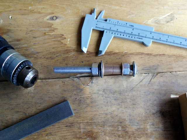
I decided instead to buy some off-the-shelf hardware from Zorotools.com. These were about $2 for a bag of 3.
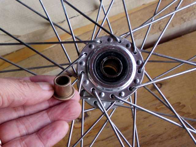
My solution would be to put one of these sleeve bearings on each side of the wheel. Then, a 3/8″ threaded rod could go straight through as an axle. I could tighten down nuts on either side of the wheel, because the flange on the sleeve would provide just enough clearance to avoid scraping the outer ring of the sealed bearing.
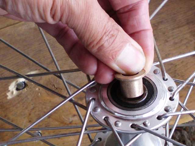
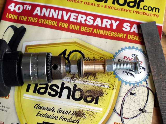
The parts that I bought were sintered bronze, not super tight on tolerance. I wanted a snug fit, but not an interference fit. I didn’t have a lathe, and the thought of paying a machinist to take off 4 mils was distasteful. So I made my own makeshift lathe, and used an ordinary file as the cutting tool.