I’m in the process of bringing up the Power Transfer Controller (PTC). When I was 16, I might have loaded everything onto the board at once, then just fired it up. Today, I take a more incremental approach, loading the minimum number of components for the next test. The board is loaded with test points, so testing has been relatively easy so far.
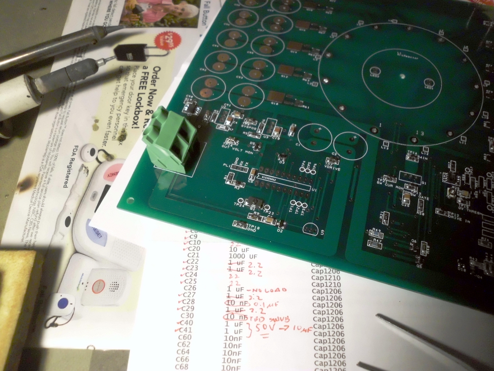
I’m soldering by hand with a pair of irons, as I don’t have an SMT hot air tool. If you want to see how…
Come to think of it, my wife has an embossing hot air wand. I might try to use that to anneal the solder joints later. Maybe.
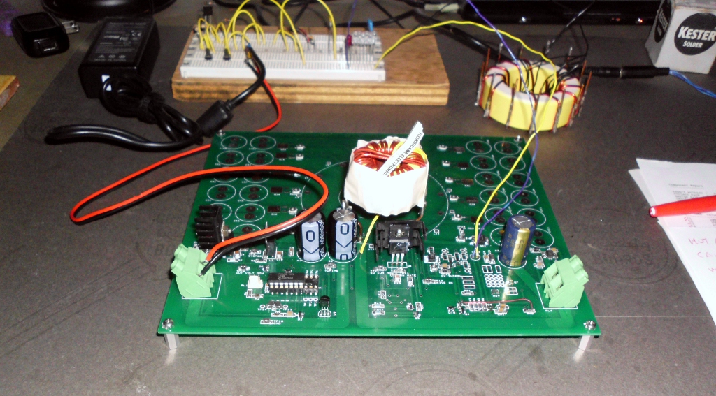
To bring the board up on the bench, I’ve substituted a laptop power brick for the solar panel, and use incandescent lamps as dummy loads. Although not all parts are loaded, the correct final devices are mounted – the sole exception being the main inductor. The final part has 25 leads, and would be hard to remove if redesign was required.
In addition to my multimeter and scope, I use little test programs to stimulate and test sections of the board. Some of the data is gathered by the PTC’s own sensors, and printed to a log file.
So far, here are the things that are working. They correspond roughly to the assembly and bringup order:
- voltage regulators
- visibility flasher
- processor
- push-button input and indicator LEDs
- sensors (characterization data below for my later use)
- analog voltage limit comparator
- basic power transfer
| Sensor | Zero Reading Base | Sensitivity | Native Reading |
|---|---|---|---|
| Input Voltage | 0 counts | 102 mV/count | 50 mV/V |
| Input Current | 106 counts | 25 mA/count | 200 mV/A |
| Mid Current | 103 counts | 51 mA/count | 100 mV/A |
| Output Voltage | 0 counts | 81 mV/count | 63 mV/V |
| Output Current | 103 counts | 51 mA/count | 100 mV/A |
| Temperature | 0 counts | 0.51 ºC/count | 10 mV/ºC |