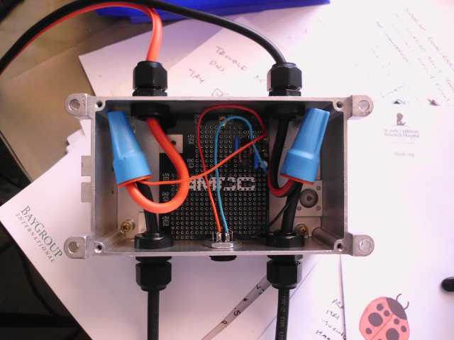
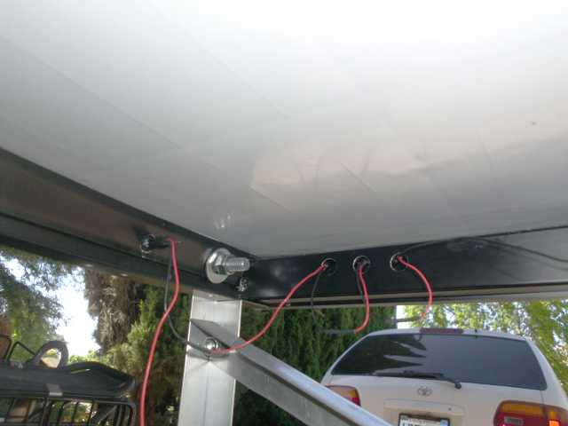
The solar trailer will be down low where a car won’t be expecting it. I can’t put a tall flag on it for visibility, as that would shade the panel. So I’d like to have flashing lights.
For a little while, I thought about using the PICAXE to drive some trailer lights. However, I want the lights to be able to work at night, too, in the unlikely event that I have to be on the road. That means battery power, and a separate flasher circuit.
Sometimes the old ways are better. By using an ancient discrete transistor circuit, I’ll be able to run off a wide range of voltage, without the need for a regulator. The last time I really did this kind of thing was about 40 years ago, as a gift for a special girl in high school.
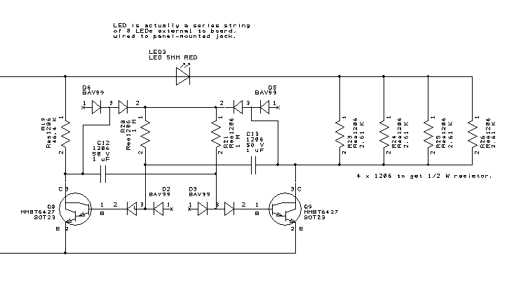
The above is a conventional astable multivibrator circuit, with a few less common options. An RC time constant of about 1 is needed for the flash rate of 1 Hz. In the old days, I would have used 10k and 100 µF, and the 100 µF would have been electrolytic. Today, I can easily find 1 uF or even 10 uF in a small surface mount ceramic caps. This implies a base resistor of around 1 MΩ. Ordinary NPN transistors would not have enough gain to brightly light LEDs with such a weak base drive, so Darlingtons are used. The diodes in series with the bases of the transistors are to protect against negative base voltages beyond what the transistors can stand. If the power supply was 9 volts or less, those diodes would not be needed. The other diodes are for anti-lockup insurance. In a simpler implementation, the base resistors are tied straight to the positive supply, but this arrangement can get into a state where both transistors are on and stay on forever. The dual diodes are used because they are common, inexpensive, and hard to put onto a PC board in the wrong orientation.


