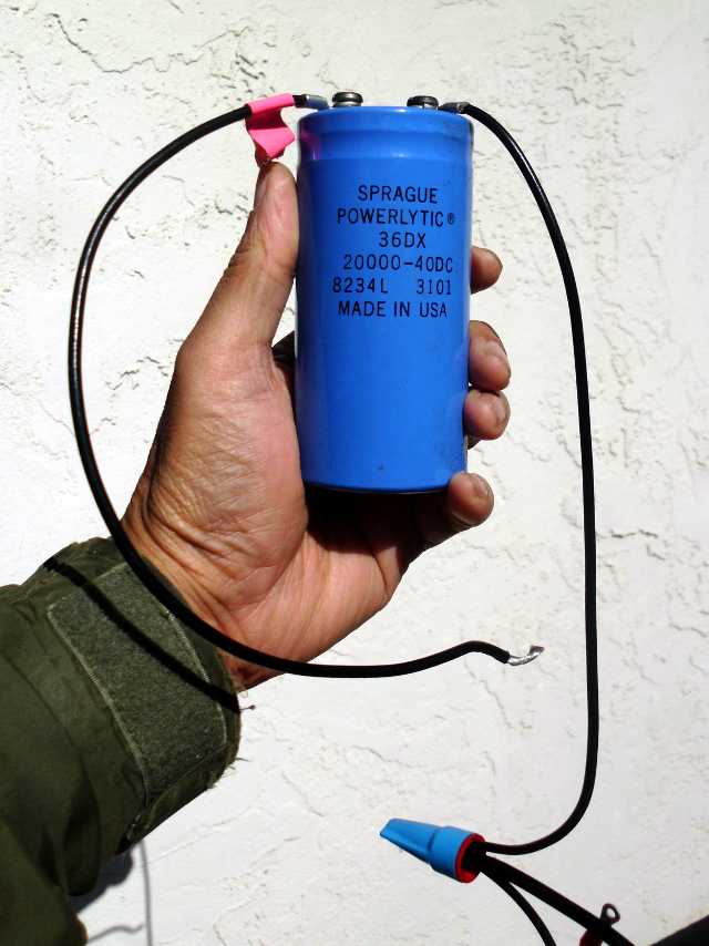
Remember that previous experiment where the motor wouldn’t start with the solar panel connected but no battery? The panel was enough to sustain the motor for running, but was not enough to start it. I took a wild guess that it might be a startup current issue. Solar panels are roughly constant current devices – they do not supply significantly more current as the load voltage is lowered. As a test, I hooked up the following:
With the capacitor, the motor gave a twitch, but still wouldn’t spin up to speed. It seemed to be a more pronounced twitch than without the capacitor, but I couldn’t be sure.
No more guessing; it was time to take a more analytic approach. I needed to get a profile of voltage and current when the motor was starting, and running. Voltage was easy – just hook up the oscilloscope. For current, I needed a sense resistor. Fortunately, I had some 0.05 ohm, 1%, 3-watt resistors lying around. Two of these in series gave me 0.1 ohm, 6 watts. Although the starting power through the resistor was likely to be much higher, I hoped that the surge would be brief enough for the resistor to withstand.

Here is the trace that was obtained:
The top trace (yellow) is the voltage across the sense resistor. Since the resistor is 0.1 Ω, each volt corresponds to 10 A of current flowing. Therefore, the peak corresponds to a surge of 48.6 A. The bottom trace (green) is of the battery voltage. At maximum voltage droop, the voltage across the motor is 27 volts minus 7 volts displayed, minus the 5 volts across the sense resistor, so perhaps 15 volts. This means that the surge power is 15V x 48.6A = 729 W. Wow! That’s about 1 horsepower.
This trace also shows that the current rapidly drops off to about 1.8 A after the motor reaches equilibrium speed, and the battery voltage levels out at a 911 mV drop, plus 182 mV for the sense resistor, giving a total drop of 1092 mV. This means 25.9 volts across the motor, meaning about 47 watts is drawn to maintain the wheel at maximum speed.
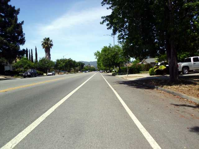
But note, the above measurements were all taken on a bike stand, not under load. What about under actual road conditions?
I decided it would be impractical to take the oscilloscope on board, so strapped on a voltmeter to measure current only.

On the road, 48 amps were drawn for a few seconds, then the bike immediately lost all power. What happened?
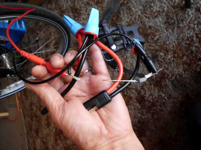

With the new current sensing scheme in place, I hit the road again.
Since I only had the voltmeter hooked up, I had to count “one-pineapple, two-pineapple, three-pineapple, …” for timing, and memorize the results. The voltmeter was not as responsive as a scope, so reported the likely 50-amp initial surge as 40 amps. Time 1 corresponds to when I saw that peak reading.
| Time (sec) | Current (amps) |
|---|---|
| 1 | 40 |
| 5 | 31 |
| 7 | 23 |
| 10 | 16 |
| @ terminal speed | 13 |
| Time (sec) | Current (amps) |
|---|---|
| 1 | 40 |
| @ terminal speed | 11 |
| Time (sec) | Current (amps) |
|---|---|
| 1 | 40 |
| 5 | 3.2 |
| @ terminal speed | 3.2 |
When I pedaled, terminal velocity uphill was reached in 5 seconds.
| Time (sec) | Current (amps) |
|---|---|
| 1 | 40 |
| 3 | 3.2 |
| @ terminal speed | 1.7 (same as on stand) |
Going downhill, terminal velocity was reached in 3 seconds. Cruising downhill with pedaling is the same as having no load as far as the motor is concerned.
| Time (sec) | Current (amps) |
|---|---|
| 1 | 40 |
| 10 | 34 |
| @ terminal speed | 17.5 |
On this very slight grade, the motor seems to be drawing perhaps 420 watts. The solar panel would not be able to keep up.
| Time (sec) | Current (amps) |
|---|---|
| 1 | 40 |
| 5 | 9.4 |
| @ terminal speed | 9.4 |
The trailer is no burden going downhill. In fact, less current is drawn by the motor, suggesting that the trailer is somehow pushing the bike. However, the solar panel still doesn’t have enough power to sustain terminal speed on its own.
This is a setback for having a batteryless, solar-powered vehicle with unlimited range. If the panel does not have enough power to sustain the motor even at cruising speed, no energy storage solution is going to help, except by charging over a long period, and discharging over a short period. I want the motor to run continuously.
All hope is not lost. I don’t care if the vehicle runs slowly, as long as it runs. Possibly I can substitute a 250-watt motor for the 750-watt one now in place.
Back to that thought about adding a capacitor instead of a battery, I think the concept was valid, but the specific implementation was insufficient. I had hooked up a 20,000 uF capacitor – 0.02 Farad. Looking at the trace above, in order to get the motor up to speed on the stand, I believe I need more like a Farad, possibly two. This is the realm of supercapacitors, and I plan to look into it.