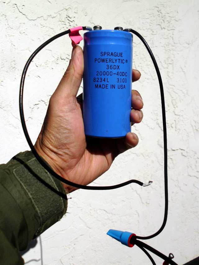
It would be a distinction to be one of the few (if any) solar bicycles running without any batteries. In a previous post, I discussed an attempt to replace the battery with a capacitor. That experiment was unsuccessful, because the capacitor did not have enough energy to overcome the starting torque of the motor. Here is the capacitor I used for that experiment:
I needed much more capacitance. Enter the world of supercapacitors, also known as boost caps or ultracapacitors. The one below has a capacitance of 50 Farads, and is no bigger than a Vienna sausage. Put another way, if a microfarad was a penny, then the big capacitor above would be $200, and the little capacitor below would be $500,000.

The difficulty with supercaps is their low working voltage. They’re still worth using in my application, though, because of their high energy density. That physically small supercap still stores over 10 times the energy of the conventional cap, in a fraction of the space.
To get a working voltage of 24 volts (30 volts peak), I plan to put 12 capacitors in series. In theory, each capacitor would then have 2.0 to 2.5 volts across it. Unfortunately, because of real-life tolerances, if I charged the string to 30 volts, I could end up with 11 of the capacitors at 2.4 volts, and the 12th one at 3.6 volts. That final capacitor would blow up, as that 2.7 working voltage rating is not forgiving.
When supercaps are put in series in this manner, there generally is a circuit to make sure that none of the capacitors get too much voltage across them. This could vary from a transformer winding with multiple taps that equalizes charging voltage through current hogging, to passive resistive dividers, to active circuits that reallocate charge, to circuits like the one I will use below. For the solar bike, there is really very little harm in throwing energy away, since the capacitors are just there to provide starting torque for the motor, not extended running power. A simple shunt regulator suffices.
The circuit above depicts one of twelve identical cells. C5 and C6 are the supercapacitors. The reason that two 50 F are put in parallel is that each supports a surge current of 27 amps, so two together give 54 amps of capability, enough for the 48 amp startup current of the motor. Actually, a single supercapacitor would probably supply the needed 48 amps, but that would be exceeding manufacturer specs. There is a 100 F version of the capacitor, but that was not used because it costs more than two 50 F capacitors, has higher ESR, and only a 36 A maximum current.
Z1 is the voltage reference. In the first prototype of the design, two forward diode drops were used instead of a zener. This arrangement turned out to be quite temperature-sensitive, but perhaps in a good way. As temperature rises, the forward voltage of an ordinary diode falls, but so does the maximum working voltage of the supercapacitors. By tuning the circuit to regulate at 2.5 volts at hot temperatures, I might then get 2.7 volts at very cold temperatures, allowing more energy to be stored in the supercapacitors. But I later realized that it would be better to have a well-controlled design, since 2.5 volts at low temperatures would be fine. The lowest voltage inexpensive Zener I could get was 2.4 volts, so that’s what I’m using. I might decide to make a universal footprint that can accommodate either a Zener or standard diode, just in case.
The voltage across the Zener is compared to a fraction of the capacitor voltage set by trim pot R12. Footprints for R9 and R10 are there in case I ever decide to use fixed resistors instead of hand tuning each circuit with a pot. The op amp used for the comparison is an MCP6001, selected for its low price, and the fact that it will work with a supply voltage down to 1.8 volts.
If the voltage gets too high, the op amp turns on power Darlington transistor Q3 to drain charge away from the capacitors. This is, in fact, one of the few situations where a Darlington transistor is ideal. Because of the low supply voltage (2.5 volts), it would be hard to supply enough gate voltage to turn a MOSFET on. And even if that were possible, the usual advantage of a MOSFET is the low resistance in saturation. Since this is a shunt regulator, the transistor needs to dissipate the excess energy, and does not go into saturation, anyway. Also, unlike an ordinary bipolar transistor, a Darlington has very high current gain, so can be driven directly with the milliamp output of the op amp.
The stack of 12 supercapacitor cells will be charged with a circuit that has a bit of intelligence, itself. If the voltage across the whole stack is 24 volts or less, full charging current of up to 10 amps will be applied. From 24 to 28 volts, the current will be limited to 2 amps. From 28 to 30 volts, 50 mA (a trickle charge). Above 29.8 volts, the charger will be turned off. With this algorithm, I hope to minimize the power that must be dissipated by the shunt regulators. Incidentally, if I ever want to go back to lead acid battery charging, all I have to do is change firmware.
As a learning exercise, I tried doing a PC board layout of one supercapacitor cell using Designspark PCB software. Amazingly, this free software does most of what used to require a dedicated workstation, and license fees of $35,000 per year. Designspark does lack a few features of the expensive software of yesteryear, but it gets the job done.
In the plot above, red is the top layer of copper, and cyan is the bottom layer. All components are surface-mounted on the top side of the board, except for the supercaps themselves, which are through hole components on the bottom. I need to refine this layout more, but the idea is that this basic layout would be repeated 12 times, stacked in series to make a single capacitor bank. The wide copper trace that connects the positive leads of the capacitors is 0.25 inch wide, and would be connected to the negative lead of the next cell stacked directly above it. The Darlington transistor will have as much copper under it as possible as a heat sink, but moreover, since the Darlingtons will be the tallest components on the board, a cold plate with heat sink grease will clamp over all of them.
August 18, 2014 UPDATE:I realize now that the pads for R9 and R10 are not really helpful. If I have a trimpot mounted, I will use it, and if there is no trimpot, resistors could still be soldered to the trimpot pads. Since layout will be easier with less parts, I’m getting rid of R9 and R10.