Bright with hope, I put my freshly-wound inductor into a test circuit. The results were disappointing – only minimal energy transfer. In brainstorming what might be wrong, I wanted to check whether the inductor was actually 234 μH, as measured by the DM4070 meter. By the formula, dI = V/L dt, with 24 volts applied for 20 μS, I would expect about 2 amps to be flowing. If the inductance was actually much higher, less current would be flowing, and less power transferred. I inserted a 1 ohm resistor into the circuit to sense the current flowing in the inductor, as shown in the schematic below.
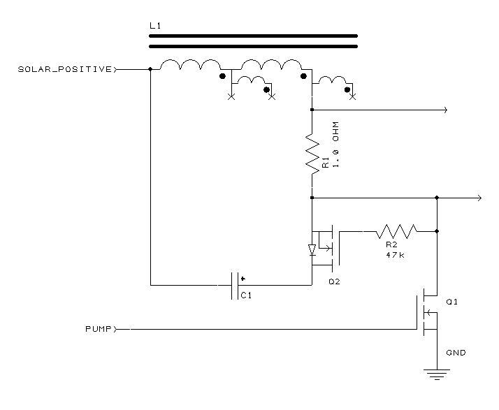
That wasn’t the ideal place to put a sense resistor, as it was in the path of discharge from L1 to C1, but it turned out to be much easier to put the resistor in that spot physically. The resistor would still give a reading of the current during the pump phase. We would simply have to disregard charging efficiency, as R1 burns up most of the power during the charge phase.
The result is below. One scope probe is at each end of the resistor, so the difference between the traces is the voltage across the resistor. Since the resistor is 1 ohm, by Ohm’s law, we can read the current in amps directly.
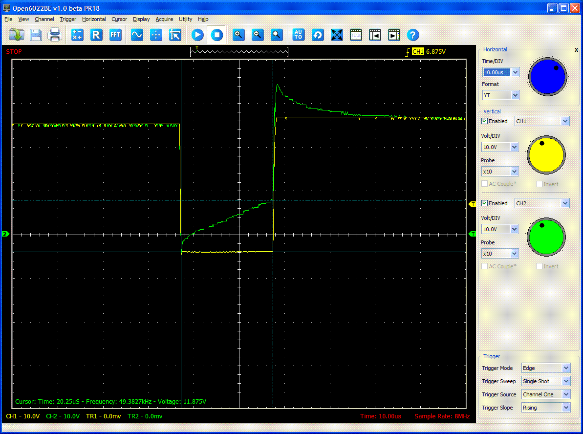
I was amazed to see about 12 amps flowing through the inductor, not 2. The formula dI = V/L dt is not so simple to use in this case, because the voltage is varying. But I could still get a feel for the inductance. If we assume the full 30 volts of drive, the 12 amps would equate to 50 μH. If driven at the ending voltage of 18 volts, the result would be 30 μH. So the inductance must be between 30 and 50 μH, a far cry from the 234 μH measured by the meter. That’s actually good news, because it means I can run at a higher frequency, and use less bulk capacitance to stiffen the input supply.
Suspicious of my good fortune, I replaced the resistor with a 50-milliohm one, and ran the test again. This time, the voltage drop across the sense resistor was not so large, but still suggested inductance in the range of 30 to 50 μH.
Oh – the original problem with efficiency? Turned out to be the resistor R2. I had put that in just to keep the gate of Q2 from floating, since I was not using synchronous rectification, yet. I had mistakenly wired R2 between the gate and drain, not the gate and source.
March 3, 2015 UpdateSome people on the allaboutcircuits forum advised me that my core was getting saturated, and moreover, it seems to have gotten semi-permanently magnetized in one direction. I took the toroid out of the circuit, and measured it with my inductance meter. One way, it measured 40-something μH, and when I reversed the leads, it measured over 1 mH. A polarized inductor – imagine that! I had unknowingly created an enormous, 1-bit magnetic core memory.
All right, I thought, so what if the core is magnetized? Is there any downside to just using it in that state, as a low-value inductor? No one was able to tell me, but experimentally I was able to determine that the energy transfer occurring with the saturated core was less than when I used an inductor of comparable size rated for 30 amps. Whether it was the fault of saturation or not, I didn’t know, but I certainly knew that the core was not efficient. I therefore abandoned the salvaged core, and ordered toroids made of known material from Amidon corporation.