Now it’s time to use that toroidal core to construct the main inductor that will be used in the power transfer controller. I needed an inductor with 12 turns of heavy wire on it, tapped at every turn. That meant 13 evenly-spaced divisions on the toroid.
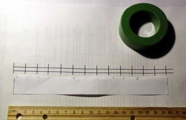
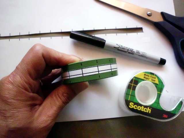
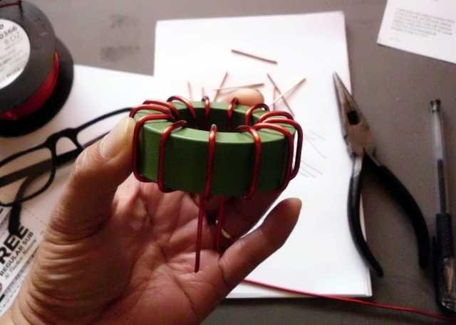
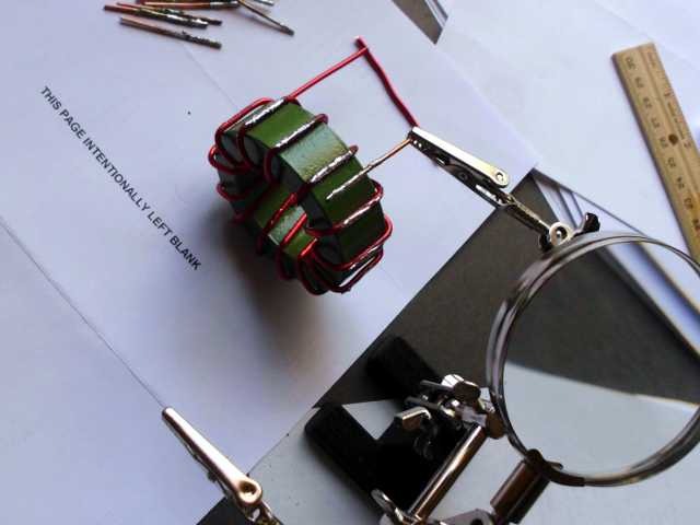
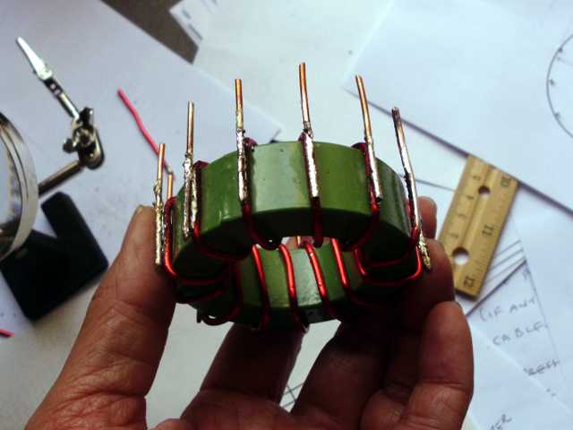
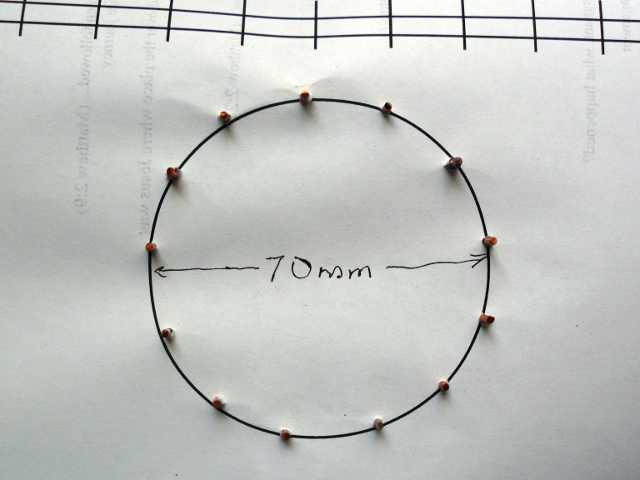
After completing the inductor, I measured the inductance of each turn. These are raw numbers, before accounting for jig inductance:
| Between pins | Measured Inductance |
|---|---|
| 1 – 2 | 4.0 μH |
| 2 – 3 | 3.9 μH |
| 3 – 4 | 3.9 μH |
| 4 – 5 | 3.9 μH |
| 5 – 6 | 4.0 μH |
| 6 – 7 | 4.0 μH |
| 7 – 8 | 4.0 μH |
| 8 – 9 | 4.0 μH |
| 9 – 10 | 4.0 μH |
| 10 – 11 | 4.0 μH |
| 11 – 12 | 4.0 μH |
| 12 – 13 | 4.0 μH |
| 1 – 3 | 8.4 μH |
| 1 – 4 | 15.6 μH |
| 1 – 5 | 25.8 μH |
| 1 – 6 | 38.9 μH |
| 1 – 7 | 55.0 μH |
| 1 – 8 | 74.3 μH |
| 1 – 9 | 96.5 μH |
| 1 – 10 | 122.5 μH |
| 1 – 11 | 152.7 μH |
| 1 – 12 | 188.0 μH |
| 1 – 13 | 0.234 mH |
I’m pleased that the inductance between turns is fairly consistent. That will translate into substantially equal voltages across the windings, which is exactly what is needed for equalizing the voltages across supercapacitors. I feel like Tony Stark creating the first miniature arc reactor in a cave!
The 234 μH across the entire inductor may be too much for my application. That would force the supply frequency way down, and necessitate using more input capacitance, making everything bigger. I might have to drive the inductor at the 8- or 9-turn tap, instead of the full 12 turns.