Everything matters. If there is one overarching summary for this experiment, that would be it. Any philosophical extensions to life in general are left as an exercise to the reader.
The goal of this experiment was to test how well different designs transferred energy. A PICAXE processor was used to provide a 20 μS pulse to the PUMP signal in the schematics below. The processor also monitored and logged the voltage across C1. The pulse was repeated once per second until that voltage reached its target value, or the test was manually stopped.
The above is a classic buck-boost or inverting converter, with the output voltage generated across C1. In the graph at the end of this article, any curve with “Schottky” in the title follows this schematic, because D1 is a Schottky diode. Resistor R1 is used to sense the current in L1. While this is not the best place electrically to sense current, it was the easiest place in which to insert a resistor mechanically on the breadboard. The learning from this part of the experiment is that even a resistance of 50 mΩ makes a noticeable difference in efficiency. On the curves pertaining to this circuit, if a resistance is listed, it is the resistance of R1. If there is no resistance listed, then R1 is a dead short.
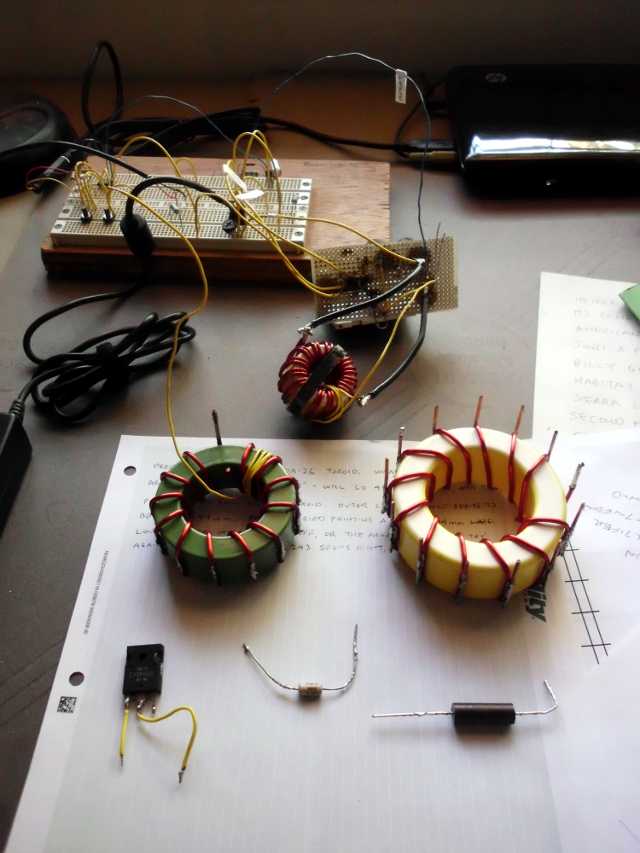
The circuit above uses the parasitic body diode of a MOSFET as the rectifier. I would have expected this circuit to be less efficient than the Schottky diode, as the transistor diode had a forward voltage of 0.65 volt when measured by my DVM, compared to 0.18 volt for the Schottky. Nevertheless, this circuit was more efficient. Possibly this was because the transistor Q2 was on the breadboard, with very short lead lengths to the capacitor being charged. When the Schottky was used, it was on leads several cm long. The learning here is that lead inductance, thickness, and length cannot be ignored, if best performance is to be achieved. Any curve on the final graph that has “body diode” in the name uses this circuit. The green core inductor actually developed more current flowing through it in 20 μS than the hurricane inductor, but delivered less energy. This suggests to me that the green core was lossy, and my takeaway is that the choice of core material is vital to efficiency.
This circuit with the Q2 gate driven by an extra winding in phase with the flyback was a first attempt at self-timed synchronous rectification. The curve labeled “hurricane sync rect unlimited” matches this circuit. This failed, for reasons to be discussed in a later article.
The final circuit above includes a capacitor C2 to limit the effective pulse width driving the gate of the synchronous rectifier Q2. The design will be discussed in a later article.