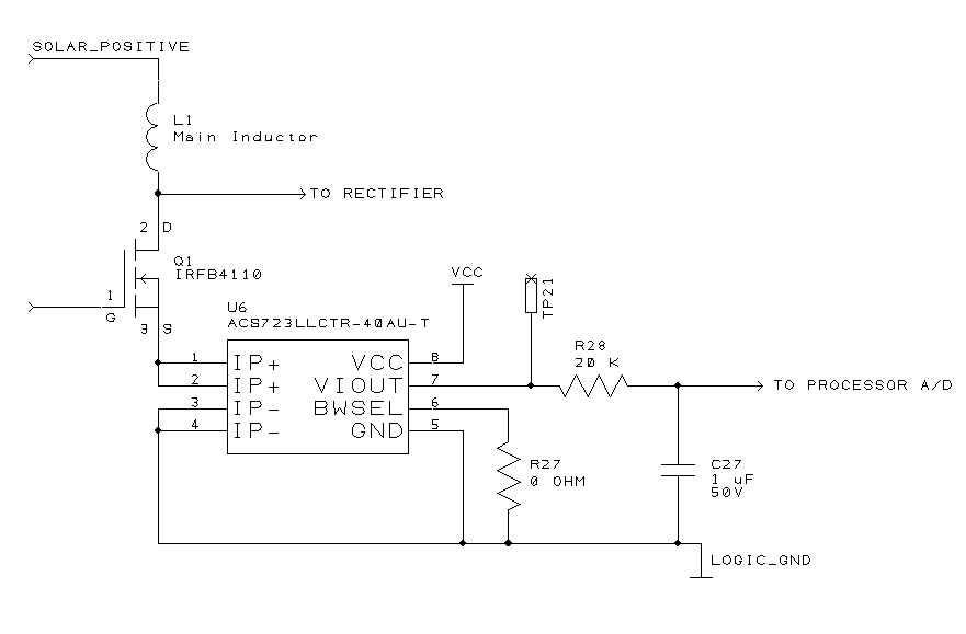
One of the goals of the Solar Bike is to have Maximum Power Point Tracking (MPPT) on the solar panel. To do that, I’ll need to measure power, and the least expensive way to do that is to measure current and voltage, then multiply the two together.
Measuring voltage is straightforward, as the PICAXE processor already has high impedance A/D inputs.
Measuring current is trickier. My original design used sense resistors. The idea is to use a low-value resistor, and when current flows through it, the voltage across the resistor will be proportional to the current. Low resistance is desired, in order not to waste power. For example, if the resistor is 1 Ω, and a current of 10 A is flowing, the power wasted in the resistor will be P = I2R = 102 * 1 = 100 watts! Ok, so maybe we use 1 mΩ, to get P = 102 * 0.001 = 0.1 watt. No problem, a normal surface mount resistor can dissipate that. But look at the voltage that would be developed across that resistor. V = IR = 10 * .001 = 0.01 volt. The A/D mode that I plan to use has a best sensitivity of 1 mV per count, translating to a resolution of 1 A. Not so good, especially if I was running between, say 2 and 3 amps. I could put an amplifier on the signal to get more resolution, but it would have to be low-noise because the small original signal.
Using a Hall Effect sensor like the Allegro ACS723 below turns out to be a better choice.

I’ll leave the fundamental principle of the Hall Effect as an exercise to the interested reader. Suffice it to say that the device has a resistance of 1 mΩ, and will give me a resolution of 100 mV/A. The output side is electrically isolated from the current path, something that doesn’t matter in the particular circuit above, but is important elsewhere in my design.
The exact part that I’m using is the ACS723LLCTR-40AU-T, which senses 40 amps full scale. It comes in a tiny SOIC-8 package, which I normally wouldn’t associate with such high currents.
Since the average currents flowing through the power transfer controller are 8 to 10 amps at best, I originally used an ACS713 part which measured 20A full-scale. But the nature of a switching converter is to have higher currents flowing (in the above circuit, it should be 40 A peak), at partial duty cycles. I found out by experiment that the 20A part actually clips at just above 20A. That is, if I have 40A pulses at 25% duty cycle, I would expect the average reading to be 40 * .25 = 10A. In fact, due to clipping, what I got was 20 * .25 = 5A as a reading. This is why I’m using a 40A part.
I also discovered that the sensor is fast, with a response time of just a few μS. When I breadboarded it, I got varying readings, depending on what the instantaneous current flow was at the precise time of each reading. R28 and C27 were added to smooth out the readings and provide an average. On the ACS713, one could put a capacitor from pin 6 to ground for exactly that purpose, but the ACS723 uses that pin for a different purpose. I decided to put in R27 in order to have a universal footprint that could be used by either the 713 or 723 in the future.