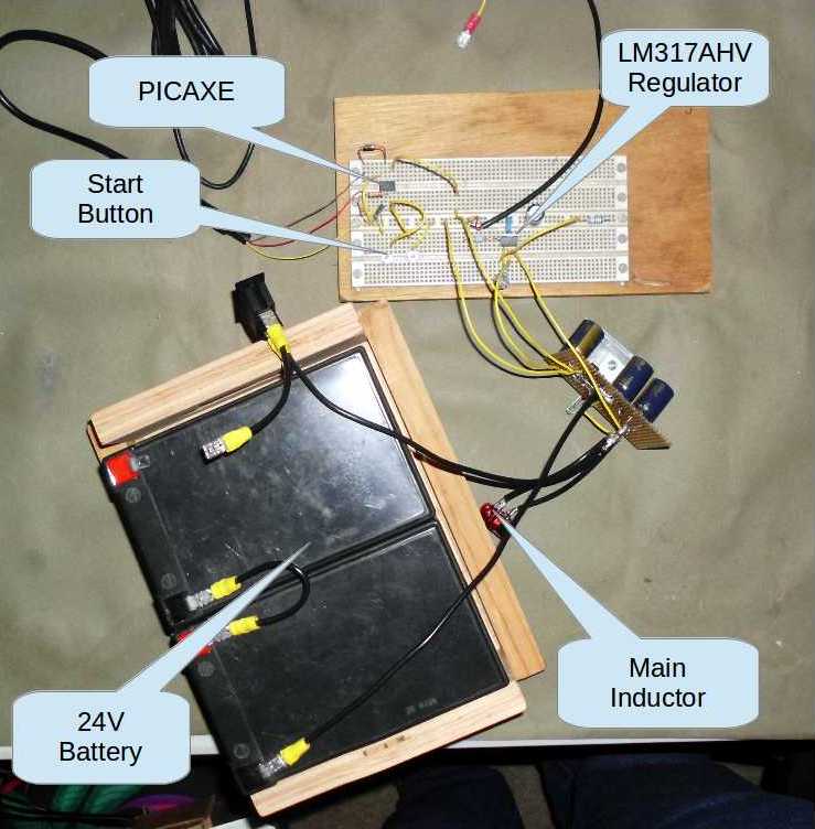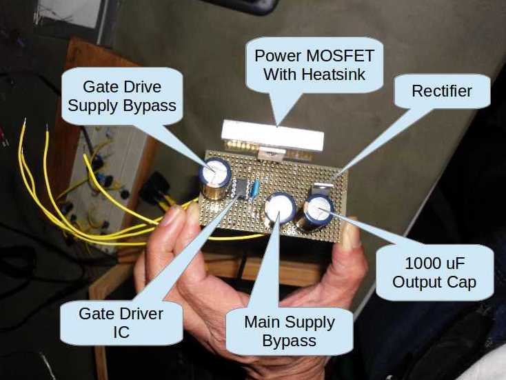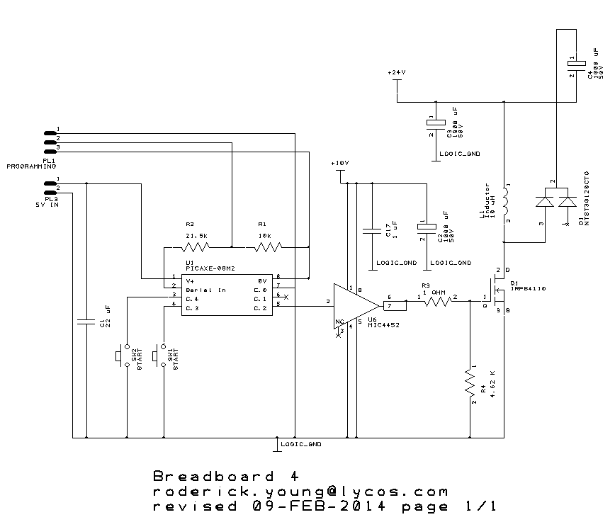
My previous attempts at a proof of concept were not very successful. In fact, they resulted in the “What’s that smell?” and “Where is that smoke coming from?” that all power supply designers know all too well. One of the problems may have been that I was trying to design my own gate driver for the main MOSFET. One of the basic guidelines for efficiency in switching power system design is that you have to bring charge to the gate of your MOSFETS, and fast. Then I had an epiphany: Why should I design a custom gate driver when I can buy one for less than a buck? So I decided to try a MIC4452 as a driver. That part theoretically has a 12 Amp peak current, although I’m using a gate resistor to limit the current further. I might use a weaker driver later, like the 4420. I’m also seriously considering using a smaller MOSFET, which would have lower gate charge. What good is having a low on resistance if you burn up all the power in slow transitions?


My program for the PICAXE controller in the above schematic will wait for the Start button to be pressed, then send out a single pulse of 3.75 μS. If we consider all components to be ideal (unrealistic), that would result in energy storage in L1 of E = ½LI² = 405 μJ. Not much, but remember, the real controller will repeat this process thousands of times a second, and use higher currents.
I hooked a voltmeter across C4, to see what energy would be transferred, if any. When I pushed the Start button, the voltage jumped from 0 to 0.43 volts! It worked. How well? The energy in a capacitor is E = ½CV², so that worked out to 92 μJ -an efficiency of about 22%. That’s terrible for a switching power supply.
One of my first theories was that the 1000 μF capacitor might not really be 1000. If the capacitor was actually a much higher value, it would be storing more energy at that voltage, which would mean my calculated value for efficiency was too low. So I built a tester to measure the capacitance. Alas, the capacitor measured out at 1048 μF, resulting in a trivial increase in efficiency.
I’m not discouraged. This experiment showed that the concept works, and now I can try to improve efficiency.