In a previous post, I discussed a circuit that I was going to use to prevent overvoltage on the supercapacitors.
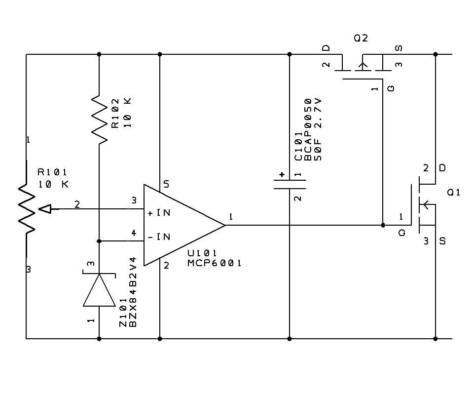
Here is a pipe dream of what the circuit should really look like:

The above circuit would require MOSFETs with very low threshold voltages, yet a sharp turn on / turn off. As far as I know, such things don’t exist today. But the theory of operation is as follows: when the voltage on the supercapacitor is too low, N-channel transistor Q1 turns off, and P-channel Q2 turns on, charging the capacitor from the power inputs at the right. When the supercapacitor is fully charged, Q2 turns off, and Q1 turns on, disconnecting the capacitor from charging, and allowing any charging current to pass to other capacitors in the series string. This circuit has the advantage of dissipating very little power once the capacitor is charged. The previous circuit simply burned off any excess energy in a Darlington, rather than pass it on to other capacitors.
Perhaps there should be a high value resistor going from pin 1 to 3 of the op-amp, to provide some hysteresis.
Actually, I have what I hope is a better idea for voltage equalization, using transformer windings. I’ll discuss that in a later post.