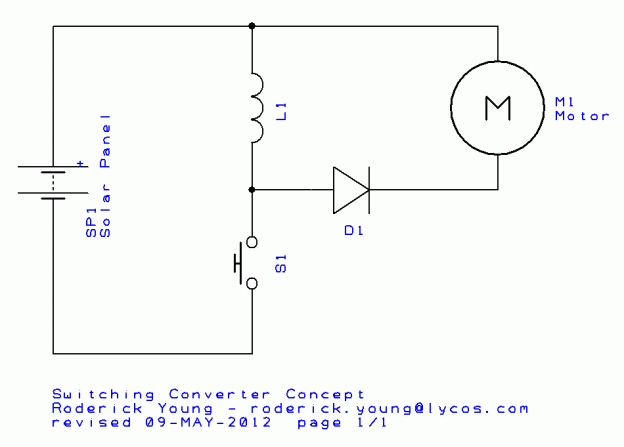
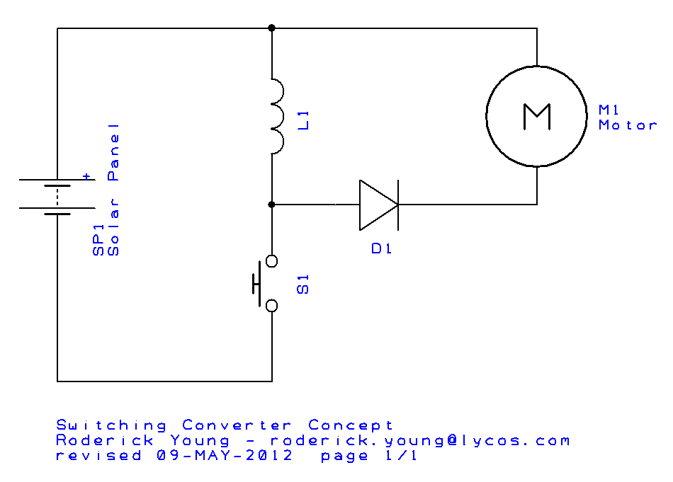
The concept of a switching power supply is not difficult. Referring to the picture above, imagine that the pushbutton switch S1 is open. The solar panel SP1 is supplying voltage, but no current is flowing anywhere in the circuit. Now suppose the pushbutton is pressed. Current begins to flow through the inductor L1 in greater and greater amounts, according to the electrical engineering equation,
V = L di/dt
Note that at this time, no current flows through the motor, yet. (As a physical analogy, think of it as water building up speed in a pipe.) Now suppose the pushbutton is released. Current continues to flow in the inductor, but this time has no where to go except through diode D1, and into the motor M1. (Back to the water analogy, the rushing water has inertia, and if you suddenly close off the pipe on one end, the water will back up and build pressure until it shoots out somewhere.) It does not matter what the voltage rating of the motor is – a short burst of current will be delivered to it. Unfortunately, it’s a one-shot deal.
But wait. We can push the button many times a second, and keep delivering power to the motor in a somewhat continuous stream. That’s the concept of a DC to DC converter. This concept has been around for a long, long time, but was highly impractical without semiconductor diodes and transistors.
In an actual circuit, there would be many more components than shown above, so that the supply can deliver just the right amount of power at any given time automatically. And the components can be arranged differently, too. Common configurations include buck, boost, buck-boost, and flyback. The configuration above is buck-boost, the topology that I will use for the solar bicycle Power Transfer Controller (PTC).
I’ll share the schematic of the Power Transfer Controller (PTC) in a later post; the design isn’t ready, yet.

