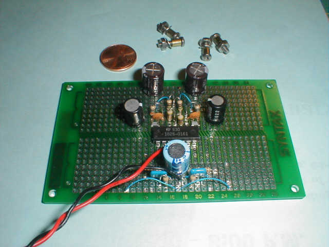
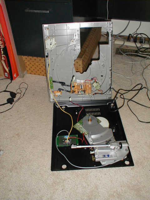
Figure 1 - The Finished Design
Figure 1 - The Finished Design
Introduction
We used to have a nice record player. It was a combination turntable/cassette/radio unit, that I got around 1981. Nine years later, we sold it for $10 at a garage sale. It was working fine at the time; we simply hadn't used it, not since we got a little CD/cassette/radio unit, which did the same thing, in half the space.
And now it is the year 2000.
At a local flea market, I recently came upon an LP record that I dearly remembered from 3rd grade. Since I had also bought a CD-RW drive, I thought it would be a simple matter to transfer the record to CD. All I had to do was ask to borrow someone's record player. That was when I discovered the awful truth. There are hardly any record players left. All the people I knew had disposed of their turntables long ago. I thought I might pick one up cheap at a flea market or thrift store. Not a chance. These sources were cleaned out, too, probably by guys like me who wanted to do the exact same thing. At Goodwill, there were a few record players, but usually missing the needles, or otherwise broken in some serious way.
I finally found a turntable at an electronics swap meet. It was a good one - a discrete component in its day - direct drive, quartz-locked. And amazingly, it was $10. It was like finding gold!
When I brought the unit home, and tried to use it, I got a few surprises.
I chose the LM324 op amp because it's designed to run off a single supply, but mainly because it's cheap and ubiquitous. There are better op amps made, but the sound quality from this circuit was fine to my untrained ear. Almost any op amp will serve for this circuit, even the dual-supply type.
Theory of Operation
The LM324, as a single supply device, cannot handle a signal that goes below ground. The divider formed by R1 and R2 set the operating point of the amplifier (that is, the voltage with no signal coming in) at about 2 volts. But why not set it at half the supply voltage? This would be possible with two 100k resistors, but the amplifier would take longer to warm up, since C4 would have to charge up to 11 volts instead of just 2. Also, since theoretically, C4 never has more than about 2 volts across it, a cheaper and more compact capacitor can be used.
The input impedance of this type of amplifier should be about 50k ohms, so the combination of R1 and R2 in parallel is in that ballpark.
This circuit should work with any power supply from about 3 volts to 32 volts. You'll need to adjust R1 and R2 to get the right operating point, while maintaining 50k input impedance. If you opt for a supply voltage on the low end, you will have to be especially careful in setting the operating point and gain, to avoid having the output clip to ground.
The typical magnetic phono cartridge will provide an input signal that swings a few millivolts above and below ground. Input coupling capacitor C1 couples the signal up to the operating point. Since this capacitor also never has more than about 2 volts across it, a multilayer ceramic cap can be used, with a 6-volt rating. If you're concerned about compactness, these capacitors come in the 0805 surface mount form factor nowadays. In fact, this whole circuit can be made thumbnail-size by employing surface-mount components.
As with any op amp, the gain of the first stage is equal to the impedance of the network between the output and the "-" input, divided by the impedance of the network between the "-" input and ground. In other words,
Gain = [Impedance of R3, R5, C2, C3] / [Impedance of R4, C4]
At "medium" frequencies, consider C4 to be a short, and C2 to be open. This gives a gain of R3/R4, which is 470k / 1.5k, or about 300. But, in fact, the capacitors are neither quite open nor shorted, so the actual gain is about 100 (20 dB).
C4 has a significant impedance at very low frequencies, and serves to reduce the gain of the amplifier at rumble frequencies. C4 is not strictly necessary, and R4 could be tied directly to ground.
R3, R5, C2, and C3 together have an impedance that reduces itself at higher frequencies. This forms the basis of the RIAA compensation - high frequencies are rolled off, creating an effective "bass boost".
To adjust the gain of the amplifier without sacrificing the RIAA equalization response, scale both R1 and C4 together as a set, and R3, R5, C2, and C3 together as a set, remembering that a capacitor's impedance is inversely proportional to its capacitance, at any given frequency. For instance, if you needed to halve the gain, you could double R4 to 3k (2.7k or 3.3k are practical values), and halve C4 to 11 uF (10 uF). Or, you could halve both R3 and R5, while doubling C2 and C3. If you wanted to double the gain, you would make the opposite adjustments. I wouldn't advise increasing R3 to more than 1 megohm, so that signals will remain large compared to noise.
Ideally, you would like the output of the circuit to be about 1 volt peak-to-peak during a loud section of music. If the output of your phono cartridge is large, then the output of this circuit may be so large as to clip against ground. You can see this if you have an oscilloscope on hand, but if, like me, you don't, you can run the output into your computer's sound card, make a recording, and examine the resultant output file (the .wav file) graphically with a player such as the freeware utility Wave Splitter. If you notice that the positive samples go all the way up to 30000, but the negative ones seem strictly limited to (say) -20000, the amplifier is clipping, and the gain will need to be reduced as explained in the preceding paragraph.
The second op amp is configured as a unity-gain voltage follower. It's not strictly necessary, but I thought the whole thing sounded better when the primary stage wasn't loaded with whatever was connected at the output. (There's no cost penalty, because the LM324 packs 4 op amps into one package.) This second stage could be used for gain, too, I suppose, but it wasn't necessary for me.
Capacitor C5 couples the output to the line input of your computer sound card, the AUX input of your stereo, or headphones. In the last case, C5 prevents the 2 volt DC operating voltage from straining the headphones. The bass response of cheap headphones is lousy, anyway, so if that's what you're using, the capacitor can be made smaller. If you're only connecting to a PC or stereo, you can probably get away without C5, since these devices generally have their own coupling capacitors embedded. Note that when the preamp is first powered up, there will be a voltage spike across C5, theoretically equal to the supply voltage, so choose a voltage rating accordingly.
C6 filters the incoming power. If the incoming power is particularly noisy, you could put a 100 ohm resistor between positive power and C6, then power the rest of the circuit off of the junction point of this resistor and C6. I chose 100 uF at 35 volts for C6, but only because I had one lying around.
None of the resistors in this design should dissipate more than 1/10 watt.
Only one channel is shown in the schematic. If you want stereo, you'll need to wire a second channel the same way. Fortunately, the LM324 has enough individual sections to build two channels.
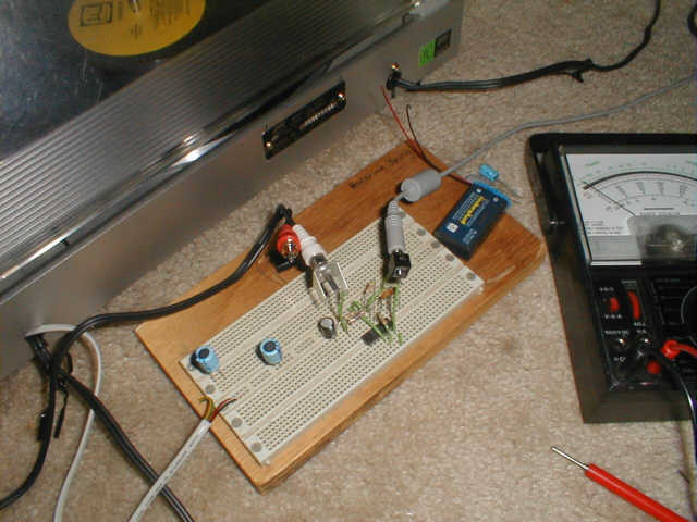
Figure 2 - The first breadboard had only one channel.
If you decide to build one of these
for yourself, I recommend that you wire only one channel of stereo, first.
This will provide a good debug opportunity. If you're like me, and don't
have an oscilloscope at your disposal at home, bringup can be accomplished
with a simple voltmeter. Look for the 2.0 volt operating voltage at the
each of the inputs to both op amp sections. If it's not there, you'll need
to debug it. When I built my preamp, I had several problems, all of which
were traceable to solder splash. Be careful when you solder, and use good
lighting. It wouldn't hurt to do a detailed visual inspection of your circuit
before powering it on.
 |
 |
|
|
|
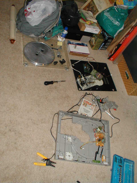
To my good fortune, this turntable already had a well-regulated 22-volt power supply inside, which I was able to tap for a few milliamps.
In place of the original RCA phono plug cable, I ran a thin shielded cable to the input of the RIAA preamp. A discarded CD-audio cable (the kind that connects a CD-ROM drive to a computer's sound card) worked beautifully. Another thin cable connected the output to a 3.5 mm stereo mini-plug.
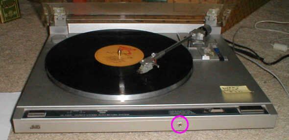
Figure 5 - The only visible difference.
When the whole thing was finished, the only visible difference was the little phone jack on the front of the turntable. But it works like a charm!